Pipe bending device in pipe bending machine

A technology of a pipe bending device and a pipe bending machine, which is applied in the directions of feeding devices, positioning devices, storage devices, etc., can solve the problems of injury to workers' pipe bending arms, hidden dangers in production safety, and limit the scope of application of pipe bending machines, so as to improve the performance of the pipe bending machine. Scope of application, the effect of improving the safety of use

Active Publication Date: 2016-04-20
江苏台和机械制造有限公司
View PDF12 Cites 9 Cited by
  • Summary
  • Abstract
  • Description
  • Claims
  • Application Information

AI Technical Summary

Problems solved by technology

The disadvantages of the above-mentioned pipe bending device are: (1) After the pipe is bent and formed, in order to avoid the rotation of the wheel mold and damage the formed pipe to be taken out stuck in the wheel mold, the wheel mold should stop rotating at this time, so that the bending arm cannot Continue to rotate, only after the worker stands in the turning area of ​​the pipe bending arm and takes out the formed pipe stuck in the wheel mold, then the drive mechanism can drive the wheel mold, pipe bending arm and clamping mold to rotate inwards synchronously through the main shaft. Clamping station, because the worker always stands in the turning area of ​​the pipe bending arm during the process of taking the pipe, when the worker is taking the pipe, due to the worker's operation error or the failure of the driving mechanism used to drive the main shaft to rotate, etc. When the pipe arm rotates, workers are easily injured by the inwardly rotating pipe bending arm, which has low safety and has buried a huge hidden danger for production safety; (2) When a part of the pipe to be bent is completed, it needs to be When bending the next part of the pipe to be bent, if the distance between the two parts to be bent is greater than the translation stroke of the clamping mold, the pipe will be moved forward by the feeding mechanism. The clamping mold blocks, so that the part of the pipe to be bent cannot reach the clamping station, so that the bending operation cannot continue, which greatly limits the scope of application of the pipe bending machine

Method used


Image

  • Pipe bending device in pipe bending machine
  • Pipe bending device in pipe bending machine
  • Pipe bending device in pipe bending machine

Examples


Embodiment Construction

[0015] The present invention will be further described below in conjunction with the accompanying drawings and specific embodiments.

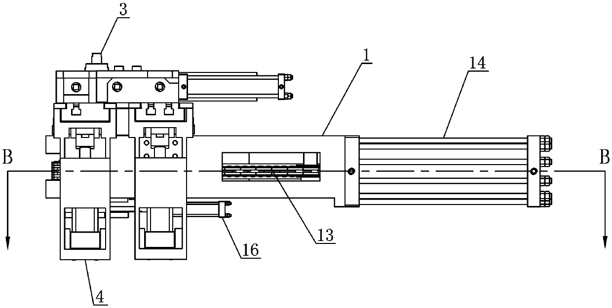
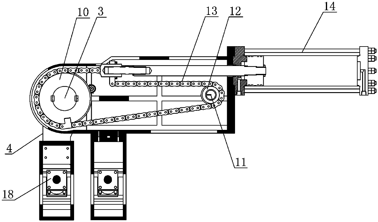
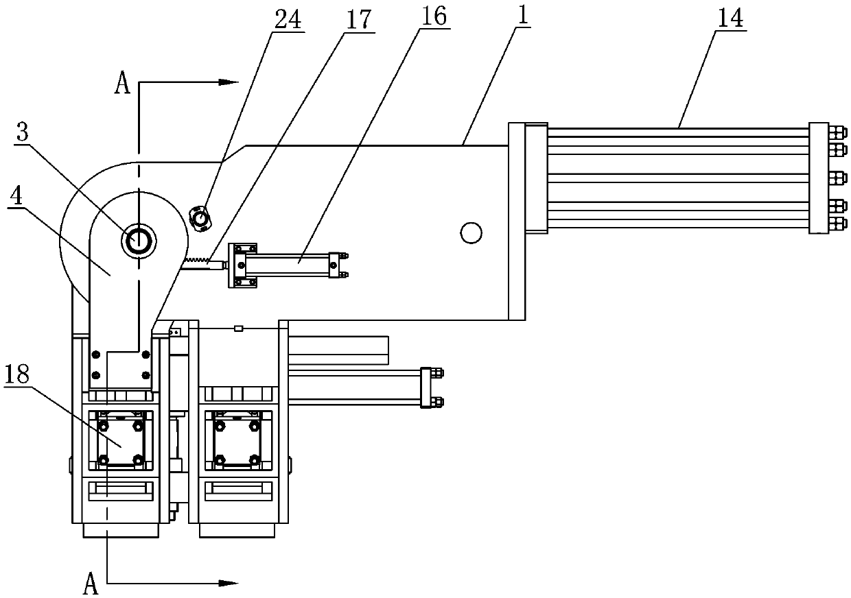
[0016] Such as figure 1 , figure 2 , image 3 , Figure 4 , Figure 5 As shown, the pipe bending device in the pipe bending machine includes: a frame 1, the front end of the frame 1 is movable and vertically supported with a main shaft 3 with a wheel mold 2 on the top, and the main shaft 3 is driven by the first driving mechanism Rotate, on the main shaft 3, the elbow arm 4 is movably sleeved, and the elbow arm 4 can rotate relative to the main shaft 3 under the drive of the second drive mechanism. A slider 6 is slidably arranged, and the slider 6 moves along the horizontal guide rail 5 under the drive of the third driving mechanism. And the outer end of the slide block opposite to the main shaft 3 is provided with a key 8, and a positioning disc 9 is fixedly set on the main shaft 3, and a keyway for inserting the key 8 is provided on the...


PUM


Abstract

The invention discloses a pipe bending device in a pipe bending machine. The pipe bending device comprises a rack, the front end of the rack is movably and vertically provided with a main shaft in a supporting mode, the top of the main shaft is provided with a wheel die, and the main shaft is driven by a first drive mechanism to rotate; the main shaft is movably sleeved with a pipe bending arm which can be driven by a second drive mechanism to rotate relative to the main shaft; the top of the pipe bending arm is provided with a horizontal guide rail, the horizontal guide rail is slidably provided with a sliding block, the sliding block is driven by a third drive mechanism to move along the horizontal guide rail and provided with a clamping die which can be matched with the wheel die to clamp a pipe, and the outer end, opposite to the main shaft, of the sliding block is provided with an insertion key; the main shaft is further fixedly sleeved with a positioning disc, and a key slot for allowing the insertion key to be inserted is formed in the positioning disc. When the pipe bending arm is located on a die clamping station, the third drive mechanism can drive the sliding block to transversely move until the insertion key is inserted into the key slot, so that the pipe bending arm and the main shaft are fixed with each other, and the clamping die can exactly clamp the pipe together with the wheel die. The pipe bending device has the advantages of being high in usage safety and wide in application range.

Description

technical field [0001] The invention relates to a pipe bending machine, in particular to a pipe bending device in the pipe bending machine. Background technique [0002] The structure of the pipe bending device currently used in the pipe bending machine is as follows: it includes a frame, and the front end of the frame is movable and vertically supported with a main shaft with a wheel mold on the top. The pipe bending arm is equipped with a horizontal guide rail on the top of the pipe bending arm, and a clamping die that can cooperate with the wheel mold to clamp the pipe is slid on the horizontal guide rail. The clamping die is driven by the clamping cylinder installed on the pipe bending arm Approach or move away from the wheel mold along the horizontal guide rail. The working process of the above-mentioned pipe bending device is: in the initial state, the pipe bending arm is in the clamping station; The other end of the material is placed between the wheel mold and the ...

Claims


Application Information

Patent Timeline
Patent Type & Authority Applications(China)
IPC IPC(8): B21D7/16B21D55/00B21D43/00
CPCB21D7/16B21D43/003B21D55/00
Inventor 徐鹏
Owner 江苏台和机械制造有限公司
Why Eureka
Try Eureka