

Lighting device and time display method
A lighting device and display method technology, applied in the field of lighting, can solve the problems of unable to display time, etc., and achieve the effect of convenient user needs
- Summary
- Abstract
- Description
- Claims
- Application Information
AI Technical Summary
Problems solved by technology
Method used
Image

Examples
Embodiment Construction
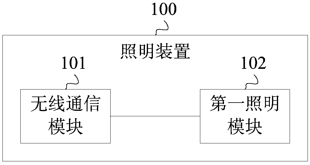
[0082] Embodiment 1 of the present invention provides an illuminating device. figure 1 It is a schematic structural diagram of the lighting device provided by Embodiment 1 of the present invention. Such as figure 1 As shown, the lighting device 100 may include: a wireless communication module 101 and a first lighting module 102 . The wireless communication module 101 can be connected with the first lighting module 102 .
[0083] The wireless communication module 101 is configured to obtain the current time through a wireless connection.
[0084] The first lighting module 102 is configured to display the current time.
[0085] Specifically, the lighting device 100 can be installed in a hall of a building, or on a roof of a living room and the like. The wireless communication module 101 can obtain the current time from other devices outside the lighting device 100 through a wireless connection.
[0086] For example, the wireless communication module 101 may establish a wire...
PUM
 Abstract
Description
Claims
Application Information