Eight-in eight-out optical cable splice box

An optical cable splice box and box body technology, used in optics, light guides, optical components, etc., can solve the problems of limited number of optical fibers in and out of the fusion splice inventory, and poor structural design of optical cables in and out, so as to achieve good temperature cycle effect and beautiful appearance. , the effect of simple structure

Active Publication Date: 2019-03-22
NINGBO YUDA COMM TECH
View PDF7 Cites 0 Cited by
  • Summary
  • Abstract
  • Description
  • Claims
  • Application Information

AI Technical Summary

Problems solved by technology

[0003] In order to overcome the above-mentioned shortcomings, the purpose of the present invention is to provide an eight-in-eight-out optical cable splice closure in the field, so that it can solve the problem of poor design of the optical cable in-out structure in existing similar products, the number of optical fibers in and out, and the amount of fiber stored in the splice tray. limited technical issues

Method used


Image

  • Eight-in eight-out optical cable splice box
  • Eight-in eight-out optical cable splice box
  • Eight-in eight-out optical cable splice box

Examples


Embodiment Construction

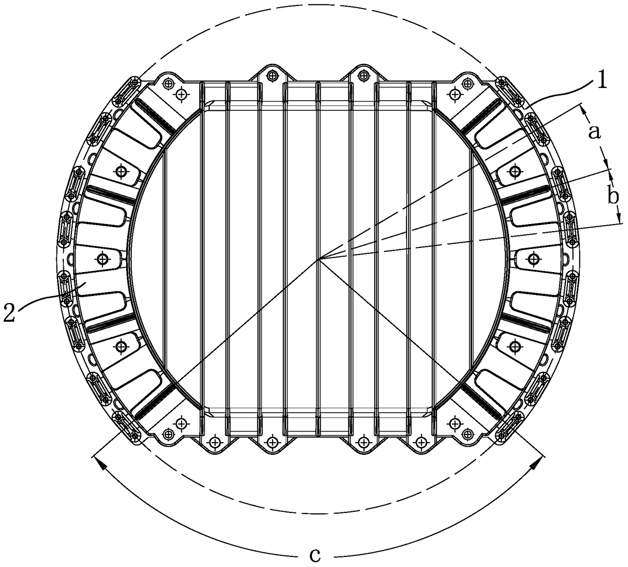
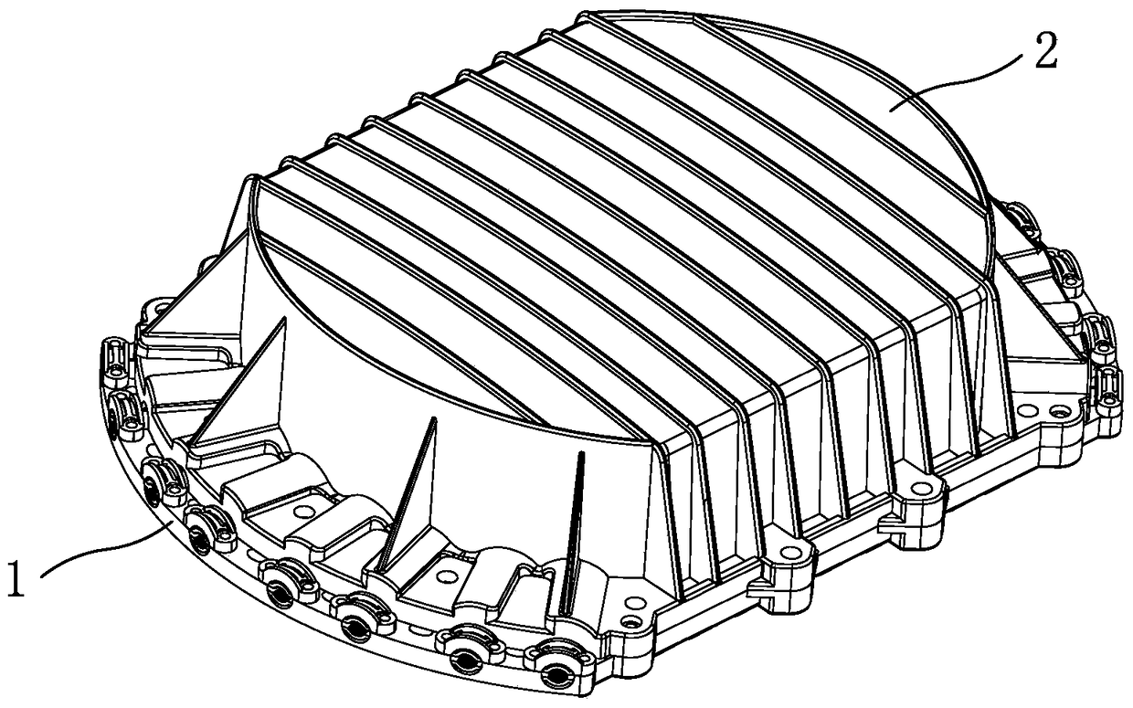
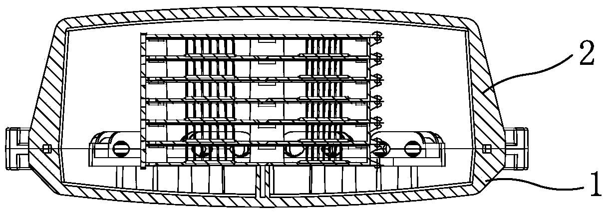
[0023] Now in conjunction with the accompanying drawings, the structure and use of the present invention will be further described. Such as Figure 1-Figure 7 As shown, the optical cable splice box includes a box body 1, a box cover 2, and a fusion splice tray 5. The edge of the notch of the inner diameter of the box is provided with a raised ring rib, and the ring rib of the box body is connected with the ring groove buckle of the box cover. Closed, the box cover and the box body are connected by screws to form a shell, the buckle is provided with sealing putty, and the outer diameter of the box cover is provided with triangular reinforcing ribs. The above housing is circular, the angle c between the two ends of the straight sides of the housing is 95 degrees, and the angle a between the inlet and outlet holes of the two housings is 10 degrees. The angle b between the inlet hole and the outlet hole between a group is 15 degrees. The two sides of the shell are symmetrically ...


PUM


Abstract

The invention relates to an optical cable connector box with eight line incoming holes and eight line outgoing holes. The optical cable connector box is designed to solve the technical problem that the structural design of existing similar products is not excellent enough. The optical cable connector box comprises a box cover, a box body and butt fusion disks. The eight line incoming holes and the eight line outgoing holes are symmetrically formed in the two ends of a shell. The optical cable connector box is characterized in that the shell is round, and straight edges are symmetrically arranged on two sides of the shell and are both provided with a screw installing lug; the line incoming holes and the line outgoing holes are formed in symmetrical arc-shaped edges on the other two sides of the shell respectively, included angles are formed between the line incoming holes or the line outgoing holes which are connected, the arc-shaped edges are provided with screw installing holes, a clamping plate is arranged at the line sleeve end in the shell, and line sleeve end ports inside and outside the shell are each provided with a line clamp. Each butt fusion disk is also round, a front clamping buckle is arranged on a front buckle of the butt fusion disk along the top edge, and a lower buckle groove is formed in the front buckle corresponding to the front clamping buckle along the bottom edge; rotating pin sleeves are symmetrically arranged at the upper end of a rear edge plate along the two ends of the outer side, the rotating pin sleeve on one side is a rear shaft buckle, and L-shaped rotating shaft pins are symmetrically arranged at the lower end along the two ends of the outer side. The butt fusion disks are arranged in a stacked mode.

Description

technical field [0001] The invention relates to an optical cable joint box, which is an eight-in and eight-out optical cable joint box. Background technique [0002] The optical cable splice box is a device that connects the end of the optical fiber, and then connects it to the optical switch through the optical fiber jumper; it is mainly suitable for communication, network systems, overhead, pipeline, direct buried and other laying methods of optical fiber. It is connected with branches to prevent material aging caused by heat, cold, light, oxygen and microorganisms in nature, and has excellent mechanical strength; at the same time, it plays the role of flame retardant and waterproof, so that vibration, impact, optical cable stretching, twisting, etc. be protected. It is generally composed of a housing, a support frame, and an optical cable fixing device. The supporting frame is the main body of the internal components. The optical cable fixing device is used for fixing th...

Claims


Application Information

Patent Timeline
Patent Type & Authority Patents(China)
IPC IPC(8): G02B6/44
CPCG02B6/4446
Inventor 徐坚荣
Owner NINGBO YUDA COMM TECH
Why Eureka
Try Eureka