Method and system for judging frequency offset in high-speed rail system

An intermediate frequency and decision technology, applied in the field of communications, can solve the problems of limited frequency offset estimation range, poor signal reception performance, unreceivable uplink signals, etc., to solve the Doppler frequency shift problem, low computational complexity, and large estimation range. Effect

Inactive Publication Date: 2018-07-06
POTEVIO INFORMATION TECH CO LTD
View PDF5 Cites 0 Cited by
  • Summary
  • Abstract
  • Description
  • Claims
  • Application Information

AI Technical Summary

Problems solved by technology

Under such frequency deviation conditions, if some measures are not taken, the uplink data cannot be received correctly
[0003] In existing frequency offset estimation algorithms, some use pilots for frequency offset estimation. For example, in LTE, the phase difference between two columns of pilots in a PUSCH subframe is used for frequency offset estimation. This method can estimate The maximum frequency deviation is around 1071Hz. If the uplink frequency deviation exceeds this range, the uplink signal will be unacceptable
In high-speed situations such as high-speed rail, the speed of the terminal may reach or even exceed 300km / h. If the carrier frequency is 2.6GHz, considering that the downlink synchronization error is 0.01ppm, the uplink frequency deviation will reach 1444+260=1704Hz. The maximum frequency offset range that can be estimated by using the pilot is exceeded, and the data will not be received at this time
[0004] Therefore, in the current uplink frequency offset estimation algorithms, some frequency offset estimation ranges are limited, and some cannot solve the Doppler frequency shift problem under high-speed conditions such as high-speed rail, and the signal reception performance is poor.

Method used


Image

  • Method and system for judging frequency offset in high-speed rail system
  • Method and system for judging frequency offset in high-speed rail system
  • Method and system for judging frequency offset in high-speed rail system

Examples


Embodiment Construction

[0046] The following will clearly and completely describe the technical solutions in the embodiments of the present invention with reference to the accompanying drawings in the embodiments of the present invention. Obviously, the described embodiments are only some, not all, embodiments of the present invention. Based on the embodiments of the present invention, all other embodiments obtained by persons of ordinary skill in the art without making creative efforts belong to the protection scope of the present invention.

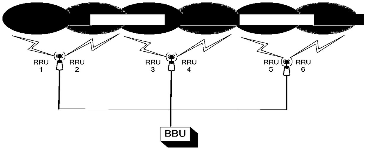
[0047] In the high-speed rail system, in order to improve the coverage of the cell, it is sometimes necessary to use a baseband processing unit (Building Base band Unit, referred to as BBU) with multiple radio remote modules (Radio Remote Unit, referred to as RRU). There are two back-to-back RRUs on the utility pole, such as figure 1 shown.

[0048] Assuming that the train departs from RRU1, within the coverage area of ​​RRU1, the end users on the train alway...


PUM


Abstract

The present invention provides a method for judging frequency offset in a high-speed rail system. The method includes: the base station obtains the received energy of the uplink signal according to the uplink signal of the user received by each RRU, and determines the maximum value of the received energy of the uplink signal; The change of the RRU corresponding to the maximum value of the received signal energy determines the positive or negative of the Doppler frequency shift; according to the uplink signal received by the RRU, the phase difference of the OFDM symbol is obtained, and according to the Doppler The phase difference is corrected by the positive or negative of the frequency shift; and the phase of the OFDM symbol is compensated according to the corrected phase difference. The invention provides a frequency offset judgment system in a high-speed rail system. The system includes a setting module, a determination module, a correction module and a compensation module. The invention has a large range of frequency offset estimation and low calculation complexity, and can solve the problem of Doppler frequency shift under high-speed conditions.

Description

technical field [0001] The invention relates to the field of communication technology, in particular to a method and system for judging frequency offset in a high-speed rail system. Background technique [0002] In the communication system, the high-speed movement of the terminal will cause Doppler frequency shift. For example, if the terminal is traveling at a speed of 300km / h and the carrier frequency is 2.6GHz, the maximum Doppler frequency shift generated is about 722Hz. In the uplink, the Doppler frequency shift caused by the movement of the terminal will be at most twice the maximum Doppler frequency deviation, that is, the terminal is traveling at a speed of 300km / h, regardless of the downlink synchronization error condition Down, the uplink frequency deviation can reach up to 1444Hz. Under such frequency deviation conditions, if some measures are not taken, the uplink data cannot be received correctly. [0003] In existing frequency offset estimation algorithms, so...

Claims


Application Information

Patent Timeline
Patent Type & Authority Patents(China)
IPC IPC(8): H04L27/26
Inventor 于小红陶雄强
Owner POTEVIO INFORMATION TECH CO LTD
Why Eureka
Try Eureka