A method and device for large frequency offset estimation in 5g NR system

A 5G NR, large frequency offset technology, applied in the field of large frequency estimation, can solve problems such as estimation failure, difficulty in obtaining frequency offset estimation results, phase ambiguity, etc., to reduce noise and multipath, improve frequency offset estimation performance, and accurate frequency Estimated effect

Active Publication Date: 2021-10-29
SHANGHAI INST OF MICROSYSTEM & INFORMATION TECH CHINESE ACAD OF SCI +1
View PDF5 Cites 0 Cited by
  • Summary
  • Abstract
  • Description
  • Claims
  • Application Information

AI Technical Summary

Problems solved by technology

However, for a large frequency offset with a phase difference greater than 7.5KHz, the phase angle rotation caused by the frequency offset may be greater than π or less than -π, resulting in phase ambiguity and resulting estimation failure
Since the demodulation reference signal (DMRS) for the physical downlink shared channel (PDSCH) in the 5G NR system is a UE-specified signal, it is not often sent. Since the maximum frequency offset that can be estimated by the DMRS is 7.5KHz, for large frequency Offset estimation may cause phase ambiguity, so it is not suitable for frequency offset estimation
[0008] In addition, if the time interval between two symbols is increased to increase the range where phase ambiguity does not occur in frequency offset estimation, for example, using a pilot with a large time interval for frequency offset estimation, it will be due to the high-speed rail environment. The Doppler frequency offset shows a zigzag change. When the UT approaches and moves away from the base station, the Doppler frequency offset changes rapidly, which makes it difficult to obtain accurate frequency offset estimation results.

Method used


Image

  • A method and device for large frequency offset estimation in 5g NR system
  • A method and device for large frequency offset estimation in 5g NR system
  • A method and device for large frequency offset estimation in 5g NR system

Examples


Embodiment Construction

[0059] The large frequency offset estimation method in the 5G NR system proposed by the present invention will be further described in detail below in conjunction with the accompanying drawings and specific embodiments. Advantages and features of the present invention will be apparent from the following description and claims. It should be noted that the drawings are all in a very simplified form and use inaccurate proportions, which are only used to facilitate and clearly illustrate the purpose of the embodiments of the present invention, rather than to limit the present invention, so they are hereby given in advance illustrate.

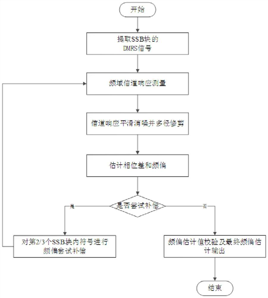
[0060] Such as figure 1 Shown is a flow chart of the large frequency offset estimation method of the present invention.

[0061] Step S1: extract initial DMRS signals at the first, second and third symbol positions of the SSB block (synchronization signal block). Since in the SSB block under the 5G NR communication system, the 0th symbol is a PSS...


PUM


Abstract

The present invention provides a large frequency offset estimation method in a 5G NR system, including: extracting DMRS signals at the three symbol positions of the SSB block; respectively performing frequency-domain channel response measurement on the DMRS signals at the first and second symbol positions ; The frequency domain channel response is smoothed and denoised and pruned according to multipath energy; the first phase difference and the first frequency offset are estimated; the DMRS signal at the 2nd and 3rd symbol positions is tried to compensate for the frequency offset; the compensation is obtained The DMRS signal repeats the steps S2-S4 to obtain the second frequency offset, and obtains the frequency offset according to the second frequency offset. The present invention also provides a large frequency offset estimation device in a 5G NR system. The large frequency offset estimation method of the present invention can complete the estimation of the frequency offset greater than the subcarrier spacing within one SSB signal block in the high-speed rail environment, which can improve the frequency offset estimation range and estimation accuracy, and further improve 5G NR communication under the high-speed rail quality.

Description

technical field [0001] The present invention relates to the technical field of mobile communication, in particular to a large frequency estimation method and device in a 5G NR medium and high-speed rail environment. Background technique [0002] In the wireless propagation environment of high-speed railway, according to the high-speed railway channel modeling of TR 38.901, the height of base station (BS) antenna is 35m, and the coverage area is about 1732m. Generally, in this kind of channel scenario, there are few scattering paths and reflection paths of the signal, and the direct path occupies the main energy of signal propagation. Therefore, the Doppler frequency spread phenomenon is not prominent. However, since the speed of high-speed rail can reach 350km / h or even faster, it will cause serious Doppler frequency shift, which will have a great impact on the performance of UT (user terminal) and BS (base station). [0003] The base station operating frequency of 5G NR i...

Claims


Application Information

Patent Timeline
Patent Type & Authority Patents(China)
IPC IPC(8): H04L27/00H04L27/26
CPCH04L27/0014H04L27/261H04L27/2628H04L27/2692H04L27/2695H04L2027/0026
Inventor 唐亮景振海陆犇卜智勇
Owner SHANGHAI INST OF MICROSYSTEM & INFORMATION TECH CHINESE ACAD OF SCI
Why Eureka
Try Eureka