Al technical title is built by PatSnap Al team. It summarizes the technical point description of the patent document.
A clutch and double-steering technology, applied in the field of clutches, can solve problems affecting the mechanical performance of vehicle equipment, single-steering clutches, and inability to move forward and backward freely, and achieve the effects of wide application range, high torque transmission, and guaranteed strength
Active Publication Date: 2018-01-02
南通棉锦纺织品有限公司
View PDF6 Cites 0 Cited by
Summary
Abstract
Description
Claims
Application Information
AI Technical Summary
This helps you quickly interpret patents by identifying the three key elements:
Problems solved by technology
Method used
Benefits of technology
Problems solved by technology
[0003] At present, most of the clutches are single-steering, that is, the output shaft of the clutch and the rotation direction of the input shaft are the same, which cannot be used for vehicle equipment that requires double steering, that is, the rotation direction of the output shaft and the input shaft of the clutch can be the same or can be The opposite of
For double-steering vehicle equipment, especially large-scale vehicle equipment such as forklifts, large agricultural machines, and non-hydraulic bulldozers, gearboxes are generally used to realize them, but there are disadvantages such as cumbersome operations and inability to move forward and backward freely, which affect the mechanical properties of the vehicle equipment.
Method used
Image
Click on the blue label to locate the original text in one second.
Reading with bidirectional positioning of images and text.
Examples
Embodiment Construction
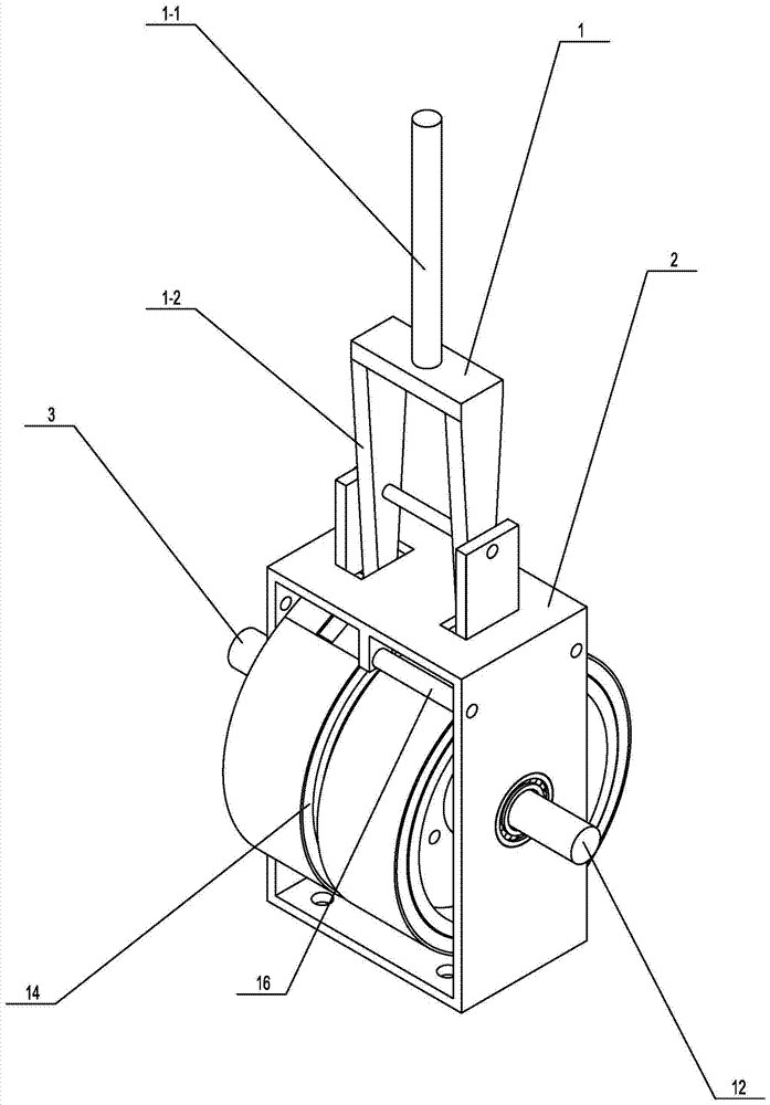
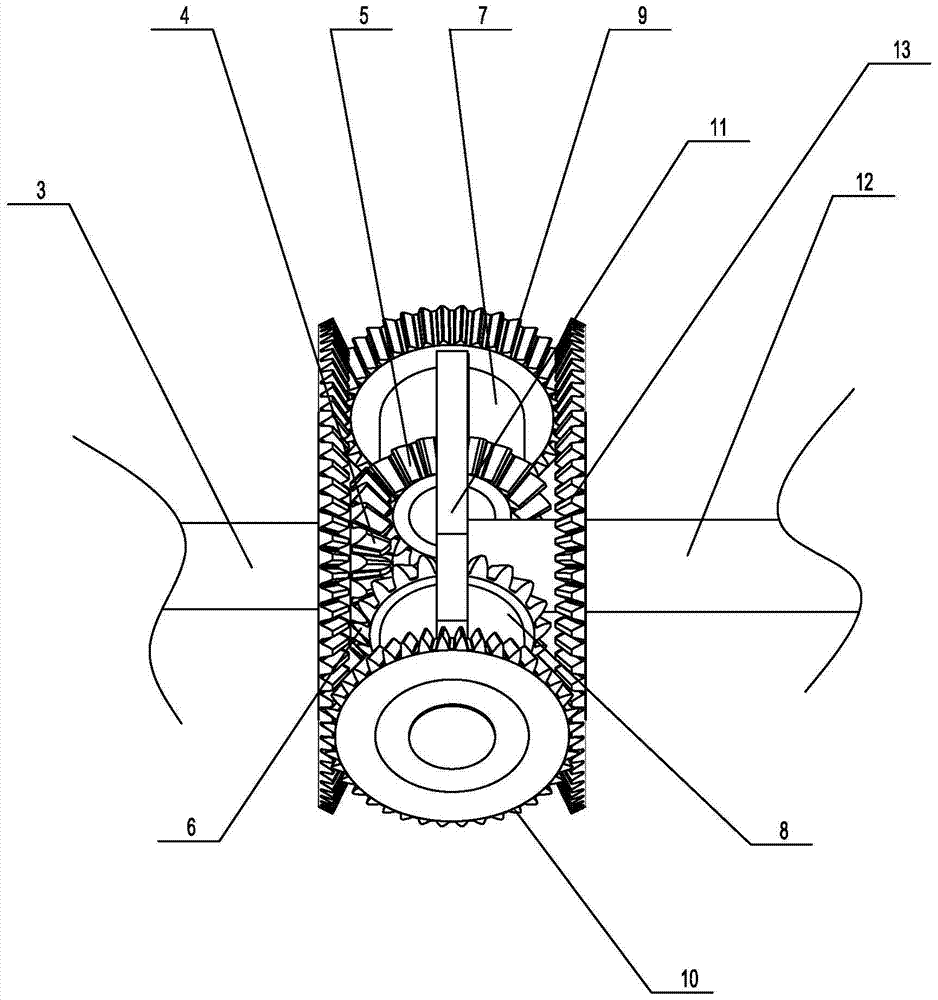
[0020] Such as figure 1 As shown, a specific embodiment of the present invention is proposed, a double steering clutch, including a manipulation member 1, and the manipulation member 1 includes a joystick 1-1 and an inverted U-shaped manipulation frame arranged under the joystick 1-1 1-2, the lower end of the control frame 1-2 extends into the hollow clutch box 2, the clutch box 2 is connected to the upper end of the control frame 1-2 through the connecting piece above it, and can be connected to the control frame 1-2 The two rods and the connecting piece are provided with through holes, and the iron is inserted through the through hole to fix the control frame 1-2 on the connecting piece above the clutch box 2; one side of the clutch box 2 is provided with a The input shaft 3 inside, the input shaft 3 can be fixed on the case wall of the clutch case 2 through the deep groove bearing, and the end of the input shaft 3 located in the clutch case 2 is provided with a drive gear 4...
PUM
Abstract
The invention discloses a double-steering clutch which comprises an operation piece, the operation piece comprises an operation rod and an inverted-U-shaped operation frame arranged below the operation rod, the lower end of the operation frame stretches into a hollow clutch box body, one side of the clutch box body is provided with an input shaft, and the clutch box body is internally provided with a drive gear arranged on the input shaft, an upper inner gear, a lower inner gear, an upper outer gear, a lower outer gear, an output shaft frame, an output shaft, brake gears, a brake drum and a brake pad, wherein the upper inner gear and the lower inner gear are meshed with the drive gear, the upper outer gear and the lower outer gear are mounted coaxial with the upper inner gear and the lower inner gear, the output shaft is located on the output shaft frame, the brake gears are located on the input shaft and the output shaft, and the brake drum and the brake pad are sequentially arranged outside the brake gears. The double-steering clutch is compact in structure, stable and firm in connection, capable of conducting bidirectional steering, flexible in braking, convenient to operate, large in torque transferred through gear meshing, capable of being applied to large vehicle equipment and worthy of wide popularization.
Description
technical field [0001] The invention relates to a clutch, in particular to a double steering clutch. Background technique [0002] The clutch is composed of a friction plate, a spring plate, a pressure plate and a power output shaft. It is located between the engine and the gearbox. Usually, the clutch is installed together with the flywheel set of the engine crankshaft. It is a component that cuts off and transmits power between the engine and the vehicle drive train. . During the whole process from starting to normal running of the vehicle, the driver can manipulate the clutch as needed to temporarily separate or gradually engage the engine and drive train, so as to cut off or transmit the power output from the engine to the drive train. Its function is to gradually engage the engine and the transmission, so as to ensure the smooth start of the vehicle; temporarily cut off the connection between the engine and the transmission, so as to facilitate shifting and reduce the ...
Claims
Application Information
Patent Timeline
Application Date:The date an application was filed.
Publication Date:The date a patent or application was officially published.
First Publication Date:The earliest publication date of a patent with the same application number.
Issue Date:Publication date of the patent grant document.
PCT Entry Date:The Entry date of PCT National Phase.
Estimated Expiry Date:The statutory expiry date of a patent right according to the Patent Law, and it is the longest term of protection that the patent right can achieve without the termination of the patent right due to other reasons(Term extension factor has been taken into account ).
Invalid Date:Actual expiry date is based on effective date or publication date of legal transaction data of invalid patent.