A method to describe the relationship between horizontal well trajectory and formation

A wellbore trajectory and horizontal well technology, applied in image data processing, 3D modeling, instrumentation, etc., can solve problems such as loss of structural features, failure to reach, and difficulty in accurately describing the real situation of the formation, and achieve good application effects

Active Publication Date: 2018-03-13
BC P INC CHINA NAT PETROLEUM CORP +1
View PDF4 Cites 0 Cited by
  • Summary
  • Abstract
  • Description
  • Claims
  • Application Information

AI Technical Summary

Problems solved by technology

This method solves the problem of the relationship between the horizontal wellbore trajectory and the formation to a certain extent, but it also has its own limitations: 1) When the wellbore trajectory crosses the formation boundary at a low angle, the horizontal well logging curve reflects The stratigraphic interface obtained is not a point, but a "interval", and it is difficult to determine the exact interface point; 2) When the adjacent vertical well logging data is projected onto the main azimuth of the horizontal well trajectory, if the stratum has a certain dip angle and gradual change or even facies change, the projected curve loses its representative structural features
This method is suitable for strata with relatively gentle geological structure and stable distribution of sand bodies. If there are complex geological problems such as lens-shaped sand bodies or muddy interlayers in the strata, and denudation at the top and bottom of the strata, it is difficult to accurately describe the true nature of the strata. However, the relationship between the wellbore trajectory and the formation cannot be accurately described.

Method used


Image

  • A method to describe the relationship between horizontal well trajectory and formation
  • A method to describe the relationship between horizontal well trajectory and formation
  • A method to describe the relationship between horizontal well trajectory and formation

Examples


Embodiment 1

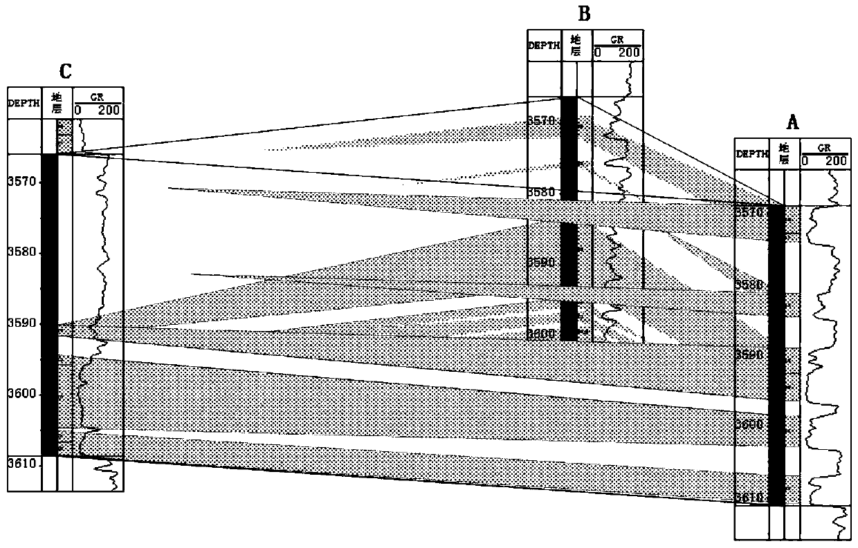
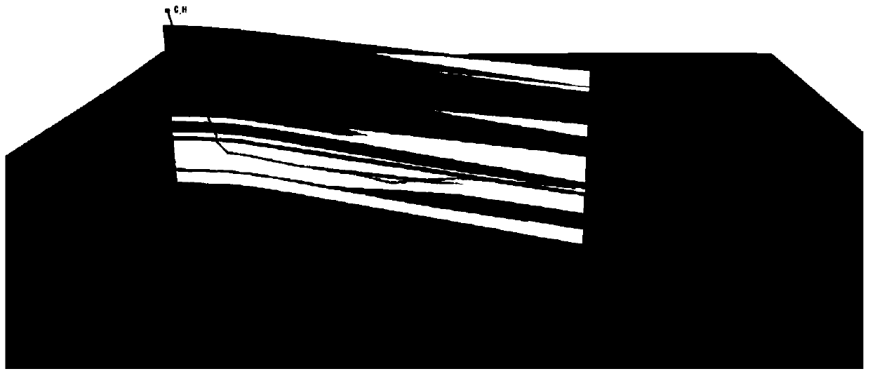
[0042] Before meticulously depicting the relationship between the well trajectory and formation of the C_H horizontal well, first determine the position of the C_H horizontal well on the reservoir structure, analyze the logging, geology, drilling and logging information of the vertical well in the area, and be familiar with the area where the C_H horizontal well is located. Geological data volume and standardization of logging curves were carried out to establish the top and bottom structure model of C_H horizontal well drilling into the target layer.

[0043] On the basis of stratigraphic comparison, three wells of Well A, Well B and Well C are selected to carry out fine sand body comparison. Among them, Well C is the pilot well of horizontal well C_H, and the horizontal well C_H borehole trajectory is drilled along the direction of Well A , Establish a grid graph of sand bodies, such as figure 1 As shown; from the sand body grid diagram, it can be seen that the target layer enco...


PUM


Abstract

The invention discloses a method for depicting the relationship between horizontal well track and strata, comprising the following steps: (1) acquiring the position information of a horizontal well on an oil and gas reservoir structure to get a geological data body of an area where the horizontal well is located; (2) standardizing the well logging curve of vertical wells and pilot hole wells in the area where the horizontal well is located; (3) performing stratigraphic comparison to determine the top and bottom limits of a drilling target stratum of the horizontal well, and building a target stratum top and bottom structure model; (4) selecting a vertical well adjacent to the horizontal well, and conducting multi-well fine sand body comparison to form a sand body fence diagram; (5) building a 3D sand body model; (6) collecting sand body slices along the horizontal well track in the 3D sand body model to get an initial model of the relationship between horizontal well track and strata; and (7) correcting sand body slices around the horizontal well track to realize visual representation and fine depiction of the relationship between horizontal well track and strata. By using the method, fine depiction of the relationship between horizontal well track and strata is realized.

Description

Technical field [0001] The invention belongs to the technical field of high-inclination / horizontal well logging evaluation, and relates to a method for describing the relationship between the horizontal well bore trajectory and the formation. Background technique [0002] With the gradual improvement of horizontal well development technology, the number of horizontal wells has increased significantly. While large-scale development of horizontal wells, new requirements have been put forward for logging, and there is an urgent need to carry out systematic research on horizontal well logging evaluation methods. The primary task of horizontal well logging evaluation is to clarify the geometric relationship between the well trajectory and the formation, determine whether the well trajectory has encountered the target layer, where in the target layer is, and the distance between the upper and lower interfaces of the target layer, etc. [0003] At present, the interpretation methods for t...

Claims


Application Information

Patent Timeline
Patent Type & Authority Patents(China)
IPC IPC(8): G06T17/05
CPCG06T17/05
Inventor 成志刚罗少成张海涛高浩锋杨小明刘天定杨智新肖飞唐冰娥陈玉林张峰杨超超
Owner BC P INC CHINA NAT PETROLEUM CORP
Why Eureka
Try Eureka