Safety rail capable of automatically winding and unwinding warning belt

A safety fence, automatic retractable technology, applied in the direction of fences, roads, building types, etc., can solve the problems of labor time waste, construction progress impact, increase the labor intensity of safety fences, etc., to achieve convenient handling and placement, convenient layout, The effect of shortening working hours

Inactive Publication Date: 2016-05-11
王永妍
View PDF8 Cites 13 Cited by
  • Summary
  • Abstract
  • Description
  • Claims
  • Application Information

AI Technical Summary

Problems solved by technology

[0003] The safety fence that people often use at present is composed of a column with a base and an elastic belt between the two columns. When arranging a safety fence at a power construction site, the elastic belt is manually retracted. When the isolatio

Method used


Image

  • Safety rail capable of automatically winding and unwinding warning belt
  • Safety rail capable of automatically winding and unwinding warning belt

Examples


specific Embodiment 1

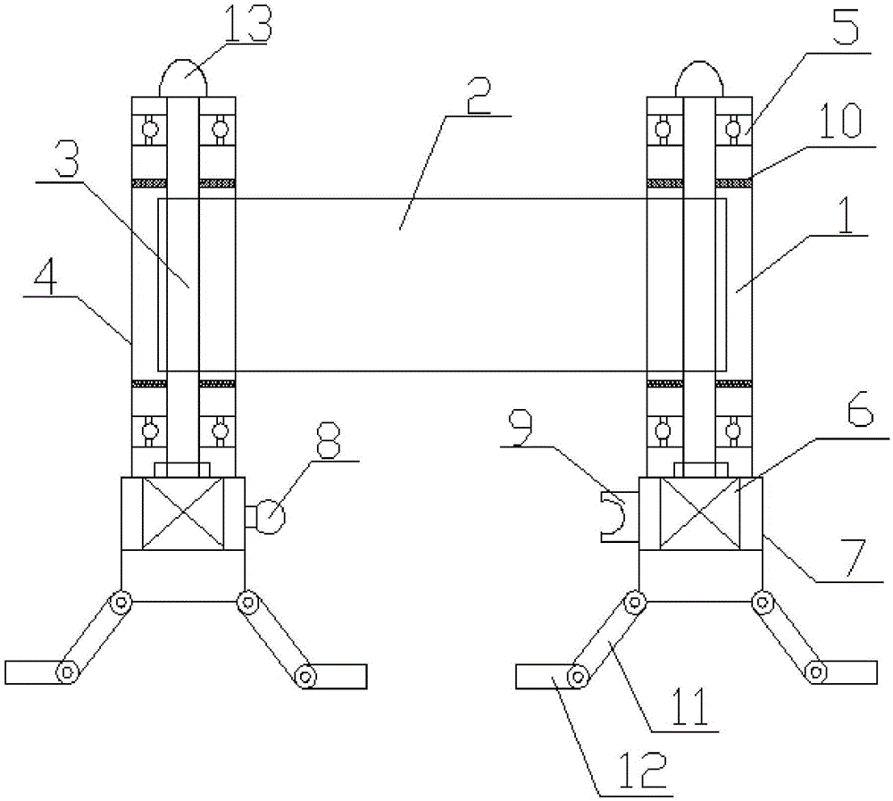
[0020] Specific embodiment one: please refer to figure 1 As shown, a safety fence that can automatically retract the warning tape includes two fence posts 1 and a warning tape 2, and the warning tape 2 is stretched between the two fence posts 1, and the fence post 1 includes a rotating Shaft 3 and shaft sleeve 4, the rotating shaft 3 is arranged in the shaft sleeve 4, the upper and lower ends of the rotating shaft 3 are fixed in the shaft sleeve 4 through bearings 5, and the lower end of the rotating shaft 3 is connected with a drive motor 6. The drive motor 6 is externally provided with a fixed casing 7 for fixing the motor, the lower end of the shaft sleeve 4 is fixed on the fixed casing 7, and the outer side of the lower end of the fixed casing 7 is provided with a support frame mechanism for supporting the ground, The warning tape 2 is wound on the rotating shaft 3, the side of the fixed shell 7 is provided with a spherical boss 8, and the adjacent fixed shell is provided ...

specific Embodiment 2

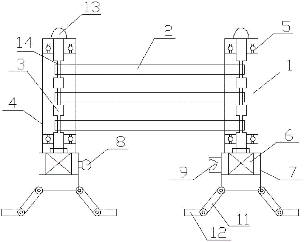
[0021] Specific embodiment two: please refer to figure 2 As shown, a safety fence that can automatically retract the warning tape includes two fence posts 1 and a warning tape 2, and the warning tape 2 is stretched between the two fence posts 1, and the fence post 1 includes a rotating Shaft 3 and shaft sleeve 4, the rotating shaft 3 is arranged in the shaft sleeve 4, the upper and lower ends of the rotating shaft 3 are fixed in the shaft sleeve 4 through bearings 5, and the lower end of the rotating shaft 3 is connected with a drive motor 6. The drive motor 6 is externally provided with a fixed casing 7 for fixing the motor, the lower end of the shaft sleeve 4 is fixed on the fixed casing 7, and the outer side of the lower end of the fixed casing 7 is provided with a support frame mechanism for supporting the ground, The supporting frame mechanism includes a first leg 11 and a second leg 12, the first leg 11 is connected to the second leg 12 through a hinge, and the first le...


PUM


Abstract

The invention discloses a safety rail capable of automatically winding and unwinding a warning belt. The safety rail comprises two rail stand columns and the warning belt, wherein the warning belt is stretched between the two rail stand columns, each rail stand column comprises a rotary shaft and a shaft sleeve, each rotary shaft is arranged in the corresponding shaft sleeve, the upper end and the lower end of each rotary shaft are fixedly arranged in the corresponding shaft sleeve through bearings, the lower end of each rotary shaft is connected with a drive motor, fixing casings for fixing the motors are arranged outside the drive motors, the lower ends of the shaft sleeves are fixed on the fixing casings, a supporting frame mechanism used for standing on the ground is arranged on the outer side of the lower end part of each fixing casing, and the warning belt winds around the rotary shafts. The rotary shafts are controlled by the motors to rotate, the purpose of automatically winding and unwinding the warning belt is achieved, and the work efficiency of workers carrying the safety rail and setting a protection area is improved effectively.

Description

technical field [0001] The invention relates to the field of safety protection equipment in the electric power industry, in particular to a safety fence that can automatically retract and retract a warning tape. Background technique [0002] The safety fence is usually used as a safety protection tool for the operation, maintenance and construction of the electric power industry. As an obstacle to prevent other personnel from entering the isolation area, it can be seen that the safety fence plays a vital role in ensuring the safety of on-site workers. [0003] The safety fence that people often use at present is composed of a column with a base and an elastic belt between the two columns. When arranging a safety fence at a power construction site, the elastic belt is manually retracted. When the isolation area is relatively large, it will be greatly increased. The labor intensity of the staff to place and install the safety fence on site will cause a lot of waste of labor t...

Claims


Application Information

Patent Timeline
IPC IPC(8): E04H17/14E01F13/02
CPCE04H17/14E01F13/028
Inventor 王永妍
Owner 王永妍
Why Eureka
Try Eureka