A hydraulic pressure relief valve

A pressure-holding valve, hydraulic technology, applied in the direction of lifting valve, valve detail, safety valve, etc., can solve the problems of reducing the reliability of the pressure relief valve protection system, multiple control mechanisms, complex structure, etc., to achieve wide applicability and overall The effect of simple structure and low cost

Active Publication Date: 2018-06-29
CHERY AUTOMOBILE CO LTD
View PDF5 Cites 0 Cited by
  • Summary
  • Abstract
  • Description
  • Claims
  • Application Information

AI Technical Summary

Problems solved by technology

Most of the pressure maintaining valves currently on the market have complex structures and many control mechanisms, which not only have high costs, but also reduce the reliability of the pressure relief valve protection system.

Method used


Image

  • A hydraulic pressure relief valve
  • A hydraulic pressure relief valve
  • A hydraulic pressure relief valve

Examples


Embodiment Construction

[0019] The specific implementation manner of the present invention will be described in further detail below by describing the embodiments with reference to the accompanying drawings.

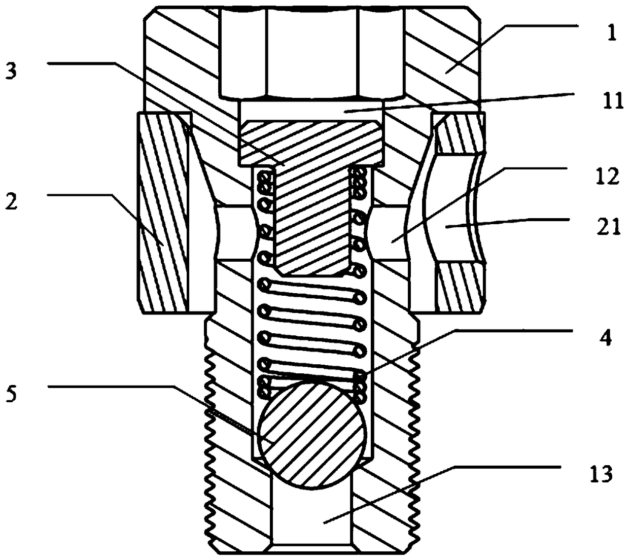
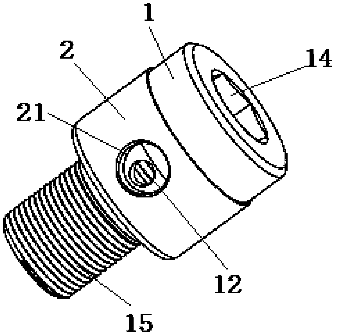
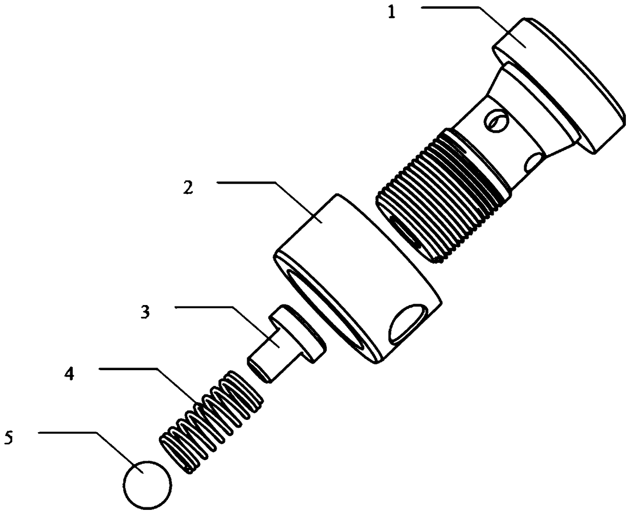
[0020] The hydraulic pressure maintaining valve of the present invention, such as figure 1 , 2 As shown, the valve body 1 is included, and the valve body 1 is the main part of the pressure maintaining valve, and the valve body 1 is covered with a valve sleeve 2 . The valve body 1 is provided with an inner chamber 11 connected to the oil inlet 13, and the connection between the oil inlet 13 and the inner chamber 11 is provided with a roller plug 5 for blocking the oil inlet 13, and the inner chamber 11 is provided with a spring 4, The upper end of the roller plug 5 is in contact with the lower end of the spring 4. The upper end of the inner cavity 11 is also provided with a spring seat 3 supported on the upper end of the spring 4. On the side wall of the valve body 1, there is an oil outlet I12...


PUM


Abstract

The invention discloses a hydraulic type pressure retaining valve. The hydraulic type pressure retaining valve comprises a valve body (1). The outside of the valve body (1) is covered with a valve sleeve (2). The valve body (1) is internally provided with an inner cavity (11) communicating with an oil inlet (13). A roller plug (5) is arranged at the joint of the oil inlet (13) and the inner cavity (11). A spring (4) is arranged in the inner cavity (11). The upper end of the roller plug (5) makes contact with the lower end of the spring (4). A spring seat (3) supported at the upper end of the spring (4) is further arranged in the inner cavity (11). A first oil outlet (12) communicating the outside with the inner cavity (11) is formed in the side wall of the valve body (1). The hydraulic type pressure retaining valve is simple in overall structure, convenient to use, good in stability, high in reliability, low in cost and extensive in applicability.

Description

technical field [0001] The invention belongs to the technical field of internal combustion engines, and relates to a valve body, in particular to a hydraulic pressure maintaining valve. Background technique [0002] With rising oil prices and increasingly stringent emission regulations, engines with low pollution, low fuel consumption, high power, and high torque have become the mainstream trend of engine design. Engine technology has been continuously improved, and the application of many new engine technologies has higher oil pressure Requirements, which requires the use of pressure relief valves to release and maintain pressure on the oil pressure in the engine chamber. The hydraulic pressure maintaining valve is used in the hydraulic system to keep the liquid in the cavity at a fixed pressure. Most of the pressure maintaining valves currently on the market have complex structures and many control mechanisms, which not only have high costs, but also reduce the reliabilit...

Claims


Application Information

Patent Timeline
Patent Type & Authority Patents(China)
IPC IPC(8): F16K17/04F16K1/14F16K27/02F02M37/00
CPCF02M37/0023F16K17/0406F16K27/0245
Inventor 段建峰
Owner CHERY AUTOMOBILE CO LTD
Why Eureka
Try Eureka