Up-moving block type booster clamping mechanism

An upper-moving block-type and mold-locking technology is applied to the field of the upper-moving block-type pressurized mold-locking mechanism, which can solve the problems of difficult processing operations, high work intensity, and eccentric center of gravity, and achieves compact structure and convenient operation. , the effect of easy mode adjustment

Active Publication Date: 2018-05-11
DEKEMO HUADA MECHANICAL DONGGUAN
View PDF7 Cites 0 Cited by
  • Summary
  • Abstract
  • Description
  • Claims
  • Application Information

AI Technical Summary

Problems solved by technology

[0002] The mold clamping mechanism of the traditional rubber injection machine is a down-moving mold clamping. The pressurized plunger is fixed on the movable platen to open and close the mold together. The length of the mold opening and closing depends on the length of the plunger. This makes the working surface unsuitable for operation. Need to sink the ground or set up a platform to operate, and the moving template is processed under the long rubber products. It needs a support frame to support the product mandrel that moves up and down, and the processing operation is difficult.
[0003] In order to overcome the problems of too high workbench and inconvenient processing of long rubber products, a pad-type mold clamping mechanism that moves up and down has appeared on the market. The block must be moved out of the mold clamping area, which makes the machine prone to eccentricity and center of gravity deviation; in addition, manual adjustment is required when using different molds, and the work intensity is high

Method used


Image

  • Up-moving block type booster clamping mechanism
  • Up-moving block type booster clamping mechanism
  • Up-moving block type booster clamping mechanism

Examples


Embodiment Construction

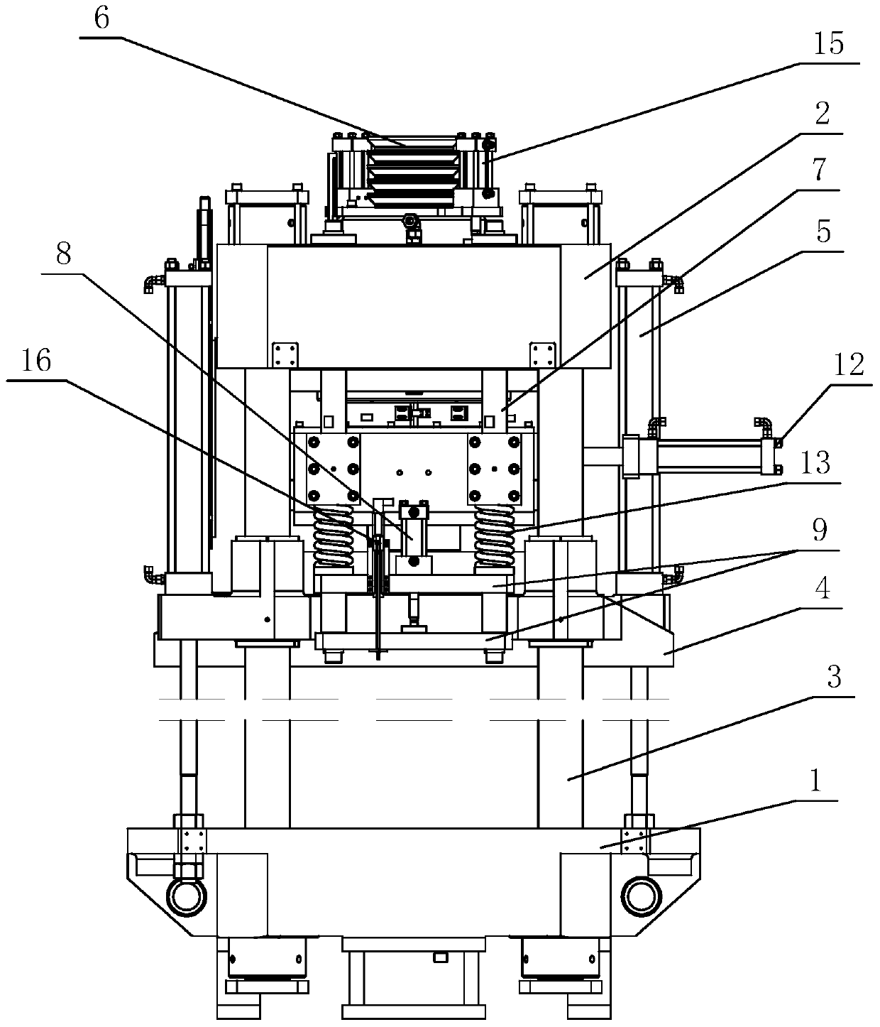
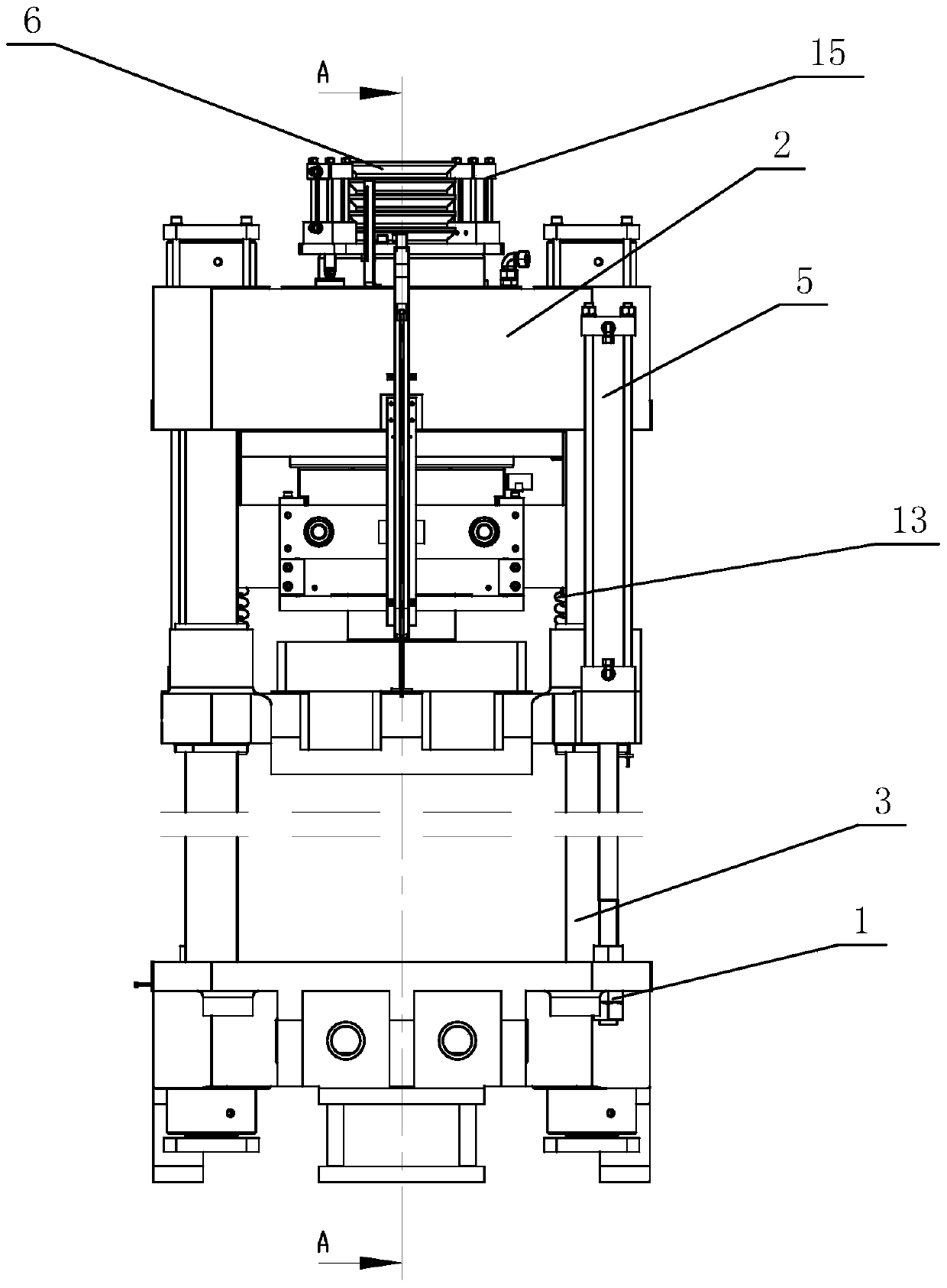
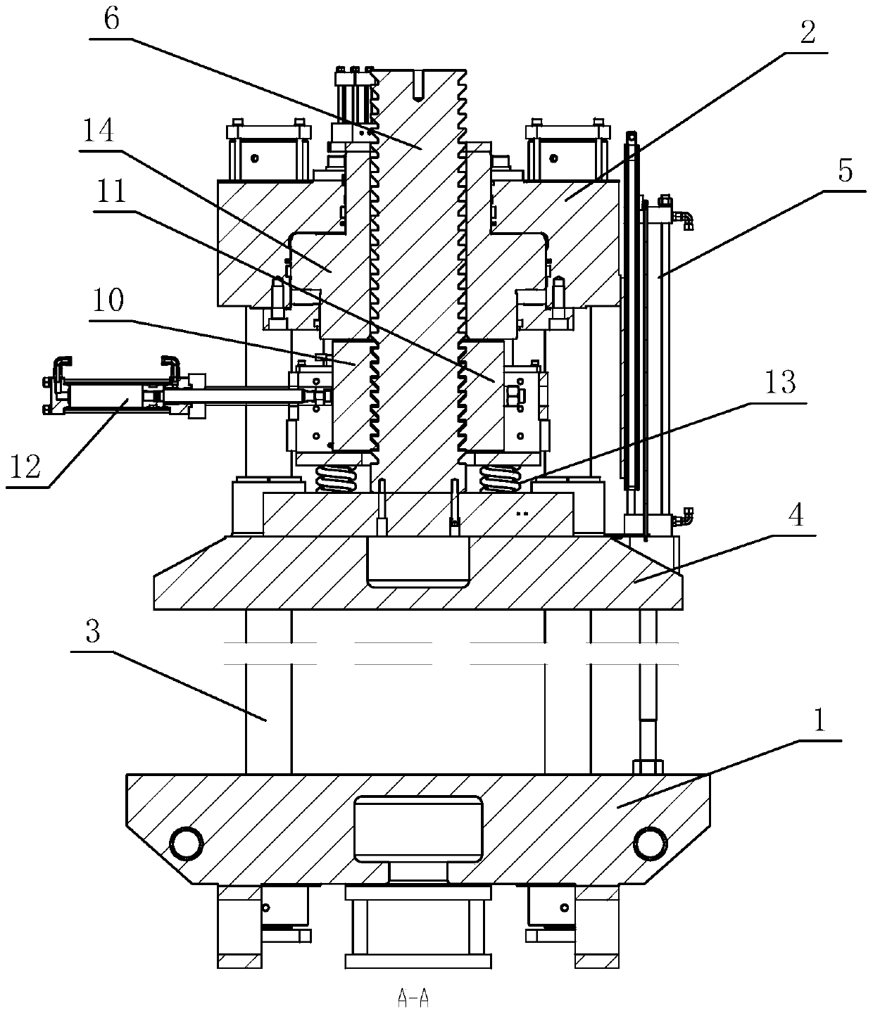
[0021] An upper moving block type pressurized mold locking mechanism of the present invention, which includes a lower template 1, an upper template 2, a column 3, a movable template 4, two quick mold clamping oil cylinders 5, and a large stud 6, and the movable template 4 passes through The column 3 can be lifted and positioned between the lower formwork 1 and the upper formwork 2, the large stud 6 is positioned on the upper formwork 2, and the lower end connects the movable formwork 4 with the column 3 as the guide to open and close up and down, and the two quick clamping cylinders 5 are fixed on the movable formwork 4. On the opposite corner, the piston rod is connected to the lower formwork 1, the upper formwork 2 is provided with a guide rod 7 extending downward, the guide rod 7 is provided with a lifting beam, and the upper formwork 2 is provided with a downwardly extending mold adjustment cylinder 8, Its piston rod connects elevating crossbeam 9, and elevating crossbeam 9...


PUM


Abstract

The invention provides an upward motion clamping block type pressurizing mold locking mechanism. The upward motion clamping block type pressurizing mold locking mechanism comprises a lower mold plate, an upper mold plate, stand columns, a movable mold plate, two rapid mold assembling oil cylinders and a large stud; the movable mold plate is positioned between the lower mold plate and the upper mold plate through the stand columns in a lifting manner, and the large stud is positioned on the upper mold plate, the lower end of the large stud is connected with the movable mold plate, and the large stud is vertically opened and closed under guide of the stand columns; the two rapid mold assembling oil cylinders are fixed to opposite angles of the movable mold plate, piston rods of the two rapid mold assembling oil cylinders are connected with the lower mold plate, guide rods extending downwards are arranged on the upper mold plate, and a lifting transverse beam is arranged on the guide rods; and the upper mold plate is provided with a downwards-extending mold adjusting oil cylinder, a piston rod of the mold adjusting oil cylinder is connected with the lifting transverse beam, a left clamping block, a right clamping block and a clamping block oil cylinder are arranged on the lifting transverse beam, and the clamping block oil cylinder is connected with the left clamping block and the right clamping block and can hold the large stud in the radial direction. The height of a working table provided in the upward motion clamping block type pressurizing mold locking mechanism brings convenience to operation, the structure is compact, and safety and reliability are achieved.

Description

technical field [0001] The invention relates to a mold locking mechanism of a rubber injection machine. In particular, it is an upper-moving block-type pressurized mold-clamping mechanism for a rubber injection machine mold-clamping mechanism with a large stud block-type pressurized mold-clamping mechanism. Background technique [0002] The mold clamping mechanism of the traditional rubber injection machine is a down-moving mold clamping. The pressurized plunger is fixed on the movable platen to open and close the mold together. The length of the mold opening and closing depends on the length of the plunger. This makes the working surface unsuitable for operation. It is necessary to sink the ground or set up a platform to operate, and the long rubber products processed by the movable template need to be supported by a support frame to support the product mandrel that moves up and down, and the processing operation is difficult. [0003] In order to overcome the problems of ...

Claims


Application Information

Patent Timeline
Patent Type & Authority Patents(China)
IPC IPC(8): B29C45/67
CPCB29C45/6707
Inventor 黄应鹏王桂秋刘华飞李高峰
Owner DEKEMO HUADA MECHANICAL DONGGUAN
Why Eureka
Try Eureka