
Backlight monitoring device and lighting machine

A technology for monitoring devices and backlights, applied in measuring devices, devices with multi-detectors, photometry, etc., can solve the problems of large error in test results, complicated and cumbersome operation, and increased Down time, and achieve the goal of monitoring brightness Effect

Active Publication Date: 2019-01-18
BOE TECH GRP CO LTD +1
View PDF14 Cites 0 Cited by
  • Summary
  • Abstract
  • Description
  • Claims
  • Application Information

AI Technical Summary

Problems solved by technology

[0002] The brightness value of the traditional JIG (lighting machine) backlight cannot be displayed independently. When monitoring the brightness of the JIG backlight, it is necessary to hold a brightness tester and point the brightness tester at the backlight to monitor the brightness value. This monitoring method comes The operation is more complicated and cumbersome, and the other is convenient due to the greater influence of human factors, the error of the test results is relatively large
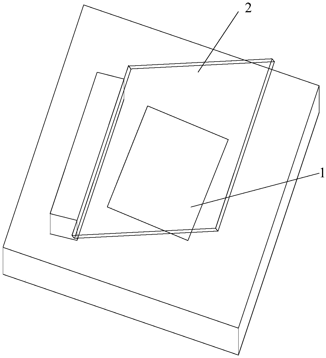
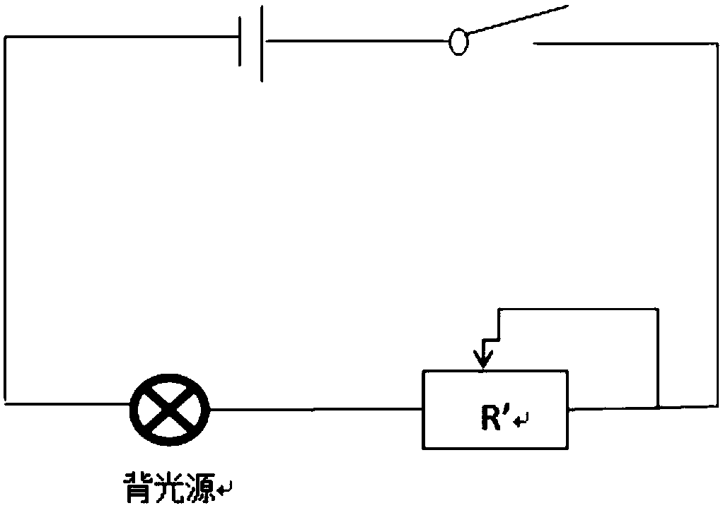
[0003] And when prior art monitors the brightness of JIG backlight source, because the adjustable switch of JIG backlight source is positioned at JIG interior, therefore, if figure 1 As shown, when adjusting the brightness of the JIG backlight, the substrate 2 covering the backlight 1 needs to be removed from the backlight 1, and then adjusted figure 2 The sliding rheostat R' in the JIG backlight adjusts the brightness of the JIG backlight, which will easily lead to the misalignment of the substrate 2, and the alignment adjustment needs to be performed again, which increases the time of the Down machine and reduces the utilization rate of the JIG equipment.

Method used


Image

  • Backlight monitoring device and lighting machine
  • Backlight monitoring device and lighting machine
  • Backlight monitoring device and lighting machine

Examples


Embodiment 1

[0047] This embodiment provides a backlight monitoring device, including:

[0048] abutment;

[0049] a fixed structure arranged on the base platform, used to fix the backlight source to be monitored;

[0050] The monitoring element fixed on the base platform is used to monitor the brightness of the backlight source to be monitored;

[0051] The display element connected with the monitoring element is used to receive and display the brightness data monitored by the monitoring element.

[0052] In this embodiment, when monitoring the brightness of the backlight source, the backlight source is fixed on the base, and the monitoring element and the display element are integrated on the base, the monitoring element can monitor the brightness of the backlight source to be monitored, and the display element can receive And display the brightness data monitored by the monitoring element, so that after the backlight source is fixed on the base, the brightness of the backlight source ...

Embodiment 2

[0073] This embodiment also provides a lighting machine, including the above-mentioned backlight monitoring device and a backlight fixed on the backlight monitoring device.

[0074] In this embodiment, when monitoring the brightness of the backlight source of the lighting machine, the backlight source is fixed on the base platform, and the monitoring element and the display element are integrated on the base platform, the monitoring element can monitor the brightness of the backlight source to be monitored, and the display element The brightness data monitored by the monitoring element can be received and displayed, so that after the backlight is fixed on the base, the brightness of the backlight can be monitored and displayed, and then the brightness of the backlight can be monitored accurately in real time.

Embodiment 3

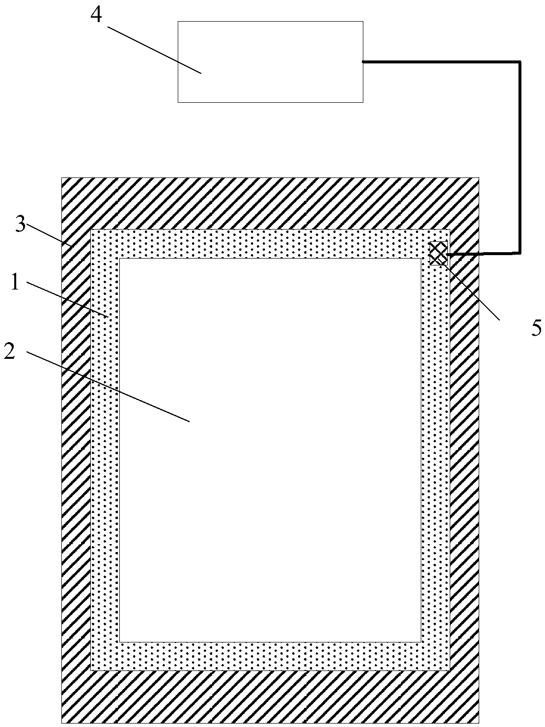
[0076] Such as Figure 3-4 As shown, the backlight monitoring device of this embodiment includes a base 3, a fixed structure arranged on the base 3, the fixed structure can fix the backlight 1 on the backlight placement area of ​​the base 3, and the backlight 1 is covered There is a substrate 2 , which is a transparent substrate and can protect the backlight 1 . The backlight monitoring device also includes a brightness adjustment element arranged on the base 3, the brightness adjustment element can provide an adjustable driving current for the backlight 1, so as to adjust the brightness of the backlight 1, so that it is not necessary to cover the backlight The substrate 2 of 1 is removed from the backlight 1, and the brightness of the backlight 1 can be adjusted. Specifically, the brightness adjustment element can be designed as a knob, and the magnitude of the driving current input to the backlight can be changed by rotating the knob, thereby adjusting the brightness of the...


PUM


Abstract

The present disclosure provides a backlight source monitoring device and a pattern generator. The backlight source monitoring device includes a base, a fixing structure arranged on the base and configured to fix a backlight source to be monitored, a monitoring element fixed on the base and configured to monitor a brightness value of the backlight source to obtain brightness data, and a display element connected with the monitoring element and configured to receive and display the brightness data obtained by the monitoring element.

Description

technical field [0001] The invention relates to the field of display technology, in particular to a backlight source monitoring device and a lighting machine. Background technique [0002] The brightness value of the traditional JIG (lighting machine) backlight cannot be displayed independently. When monitoring the brightness of the JIG backlight, it is necessary to hold a brightness tester and point the brightness tester at the backlight to monitor the brightness value. This monitoring method comes The operation is relatively complicated and cumbersome, and the other is convenient due to the greater influence of human factors, and the error of the test results is relatively large. [0003] And when prior art monitors the brightness of JIG backlight source, because the adjustable switch of JIG backlight source is positioned at JIG interior, therefore, if figure 1 As shown, when adjusting the brightness of the JIG backlight, the substrate 2 covering the backlight 1 needs to ...

Claims


Application Information

Patent Timeline
Patent Type & Authority Patents(China)
IPC IPC(8): G01M11/02G02F1/13
CPCG01M11/0207G02F1/1309G01J1/4228G01J1/44G01J2001/4247G09G3/3406G09G2320/0626G09G2360/145
Inventor 梁团李朝垒赵双会刘园张玉兵罗刚王军曲毅
Owner BOE TECH GRP CO LTD
Learn More