A Buoy Type High Frequency Ground Wave Radar System

A technology of high-frequency ground wave radar and ground wave radar, which is applied in the radio wave measurement system, radio wave reflection/re-radiation, utilization of re-radiation, etc., can solve the problems that single-station radar cannot be added to ocean monitoring, etc., and achieve wireless Humanized on-duty, to achieve the effect of shore-based personnel monitoring

Active Publication Date: 2018-05-04
ZNPL OCEAN DETECTION SYST ENG
View PDF5 Cites 0 Cited by
  • Summary
  • Abstract
  • Description
  • Claims
  • Application Information

AI Technical Summary

Problems solved by technology

Therefore, the current frequency resources in the high frequency band can no longer support more single-station radars to join ocean monitoring, which has become one of the most important social factors restricting the promotion and application of ground wave radars

Method used


Image

  • A Buoy Type High Frequency Ground Wave Radar System
  • A Buoy Type High Frequency Ground Wave Radar System
  • A Buoy Type High Frequency Ground Wave Radar System

Examples


Embodiment 1

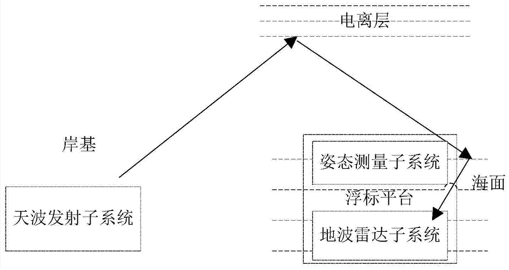
[0044] Embodiment 1. The present invention provides a buoy-type high-frequency ground wave radar system, such as figure 1 As shown, the system includes a buoy platform, a sky-wave transmitting subsystem, a ground-wave radar subsystem, and an attitude measurement subsystem; the system is used for inversion of sea wind, wave and current by ground-wave radar.

[0045] The buoy platform is the sea carrier of the ground wave radar, and its structure does not need to be limited, as long as it can be used as the carrier of the ground wave radar deployed at sea.

[0046] The sky-wave transmitting subsystem is set on the shore base to emit high-frequency electromagnetic waves. The high-frequency electromagnetic waves are refracted by the ionosphere to the sea surface, reflected by the sea surface, and received by the ground-wave radar subsystem as sky-wave signals.

[0047] The attitude measurement subsystem measures and obtains the attitude data of the buoy platform in real time.

[...

Embodiment 2

[0051] Embodiment 2, according to the scheme given in the above embodiment 1, aiming at the effect of the buoy platform, in this embodiment, in order to make the buoy platform have certain wave following, stability, and resistance to sea conditions above level 5, The following implementation is given:

[0052] Such as figure 2 As shown, the buoy platform is composed of a main buoyancy body and an instrument cabin, and the main buoyancy body includes three connecting buoy body frames, twelve sets of connecting bridges and six buoyancy cabins.

[0053] Three floating body frames are arranged in parallel, and two adjacent floating body frames are respectively connected to each other by 6 sets of connecting bridges, and two buoyancy cabins are fixed at both ends of the bottom of each floating body frame.

[0054] The buoyancy frame and connecting bridge are made of stainless steel.

[0055] The buoyancy cabin is a cabin structure, using a steel frame as a supporting frame, the ...

Embodiment 3

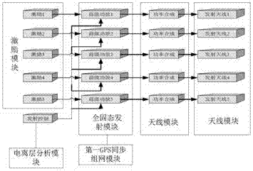
[0057] Embodiment 3, according to the sky-wave transmitting subsystem given in Embodiment 1, such as image 3 As shown, this embodiment provides a specific implementation form, but in specific implementation, it may not be limited to this form.

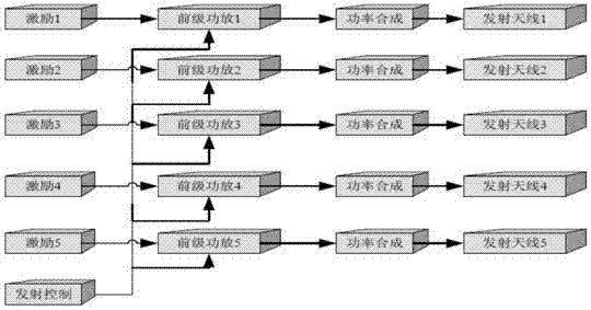
[0058] The sky-wave transmitting subsystem in this embodiment is composed of an antenna module, an all-solid-state transmitting module, an excitation source module, a first GPS synchronous networking module, an ionospheric analysis module and a sky-wave transmitting control module.

[0059] The antenna module is a logarithmic periodic antenna array, and each antenna in the antenna array emits a high-frequency linear frequency-modulated continuous wave signal, which is a high-frequency electromagnetic wave. In order to further illustrate the arrangement of the antenna array, a special example is as follows: the antenna module is composed of 5 horizontally polarized logarithmic periodic antenna elements arranged in a 1×5 linear array, a...


PUM


Abstract

The invention discloses a buoy-type high-frequency ground wave radar system. The buoy platform is used as the sea carrier of the ground wave radar; the sky wave transmitting subsystem is arranged on the shore, and high-frequency electromagnetic waves are emitted, refracted by the ionosphere and reflected by the sea surface. The sky wave signal is formed; the attitude measurement subsystem measures and obtains the attitude data of the buoy platform in real time; the ground wave radar subsystem uses the ground wave radar to receive the ground wave signal, processes and forms the ground wave Doppler spectrum; simultaneously receives the sky wave signal, and analyzes it in the frequency domain The sky-wave Doppler spectrum is formed after ionospheric disturbance compensation; the ground-wave radar subsystem reconstructs the actual geographic coordinate system based on the attitude data measured by the attitude measurement subsystem, and then the ground-wave or sky-wave Doppler spectrum is reconstructed in the reconstructed actual geographic coordinate system. The Le spectrum is used to invert the wind, wave and current data; the sky-wave transmitting subsystem and the ground-wave radar subsystem are time-synchronized through GPS synchronous networking. The system is capable of detecting sea areas at any distance and is suitable for remote sea detection.

Description

technical field [0001] The invention belongs to the technical field of marine environment monitoring. Background technique [0002] The economic relationship between human beings and the ocean is developing continuously along the order of "point-line-surface-body", and this development has a tendency to accelerate. The ocean is becoming more and more important, and the influence of the ocean on human beings is also increasing, from the level of human survival to the economic level, and even rise to the level of politics and international relations. However, human beings' ability to monitor the ocean has always lagged behind human ocean practice activities, and currently basically stays at the level of "points" and "lines", which is far from meeting the requirements of real-time monitoring of the "surface" and "body" of the ocean. need. [0003] Weakness in marine monitoring capabilities is a major problem that will long-term affect my country's development of marine econom...

Claims


Application Information

Patent Timeline
Patent Type & Authority Patents(China)
IPC IPC(8): G01S13/88
CPCG01S13/003G01S13/88G01S13/0218G01S13/874G01S13/95G01S2013/0227Y02A90/10G01S7/032G01S7/411G01S13/882
Inventor 许家勤曹俊陈智会吴雄斌邱克勇陈媛媛宋国胜李秀王鹏李杰
Owner ZNPL OCEAN DETECTION SYST ENG
Why Eureka
Try Eureka