
Universal interchange clutch based on intelligent lock

A clutch and smart lock technology, applied in the field of security and smart door lock control, can solve problems such as the inability to directly install old doors, increase the production cost and management cost of door lock manufacturers, and the inability to directly exchange the left and right directions of the door lock.

Inactive Publication Date: 2016-06-01
YUNDING NETWORK TECH BEIJING
View PDF7 Cites 4 Cited by
  • Summary
  • Abstract
  • Description
  • Claims
  • Application Information

AI Technical Summary

Problems solved by technology

[0004] When installed on a new door, since the general manufacturer has already determined the door opening direction when the door lock leaves the factory, the left and right directions of the door lock cannot be directly exchanged, so the manufacturer is required to produce two different door locks for left-opening doors and right-opening doors. , which will greatly increase the production cost and management cost of door lock manufacturers
[0005] When installing on the old door, the user's door has already been opened with installation holes according to the previous door lock specifications, and the newly purchased electronic smart lock cannot be directly installed on the old door due to the different lock bodies and other reasons.
If you install a newly purchased electronic smart lock, you need to re-open the hole on the door to install it; sometimes even because the opening on the door is not easy to adjust and change the hole, it cannot be installed, so many users want to replace the electronic smart lock, but Abandoned the use of electronic smart locks due to the inability to install

Method used


Image

  • Universal interchange clutch based on intelligent lock
  • Universal interchange clutch based on intelligent lock
  • Universal interchange clutch based on intelligent lock

Examples


Embodiment Construction

[0029] In order to enable those skilled in the art to better understand the solution of the present application, the technical solution in the embodiment of the application will be clearly and completely described below in conjunction with the accompanying drawings in the embodiment of the application. Obviously, the described embodiment is only It is an embodiment of a part of the application, but not all of the embodiments. Based on the embodiments in this application, all other embodiments obtained by persons of ordinary skill in the art without creative efforts shall fall within the scope of protection of this application.

[0030] It should be noted that the terms "first" and "second" in the description and claims of the present application and the above drawings are used to distinguish similar objects, but not necessarily used to describe a specific sequence or sequence. It is to be understood that the data so used are interchangeable under appropriate circumstances such...


PUM


Abstract

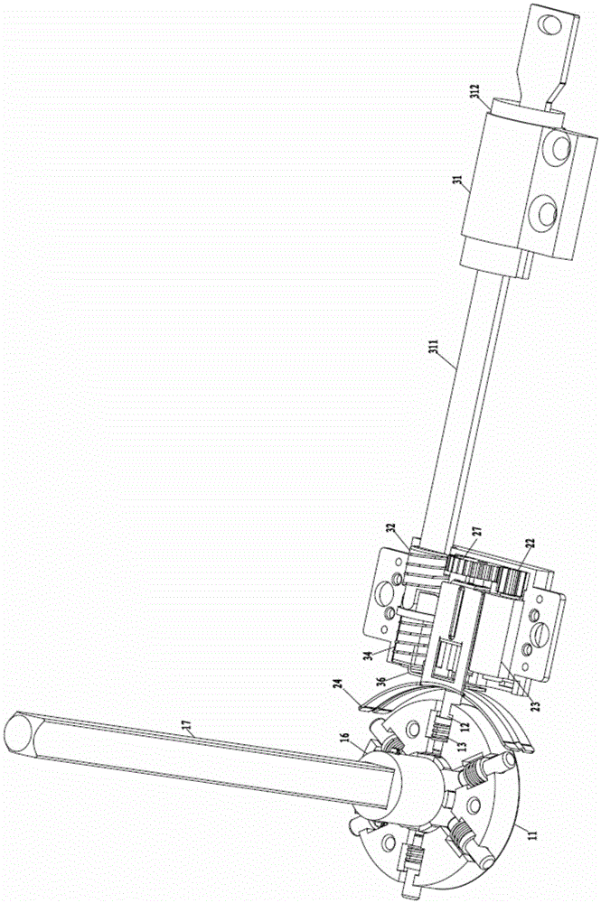
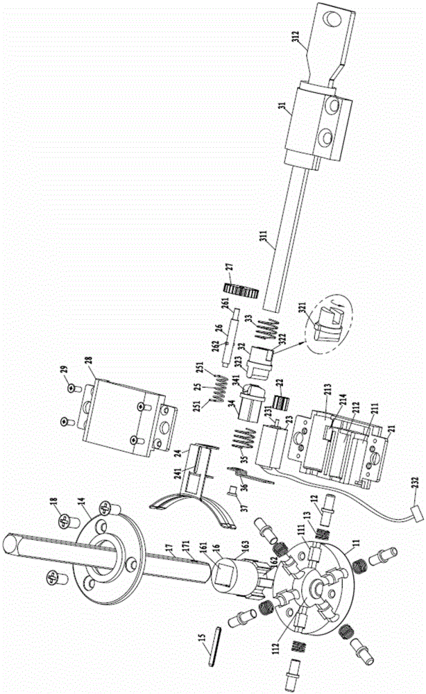
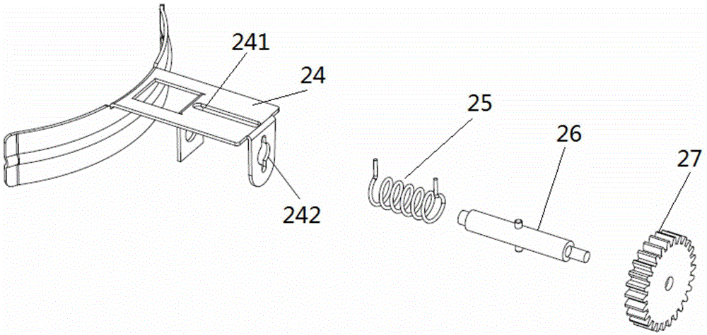
The invention provides a universal interchange clutch based on an intelligent lock. The universal interchange clutch comprises a clutch device, a clutch driving device and a mechanical key driving device, wherein the clutch device comprises a clutch base, a plurality of clutch bolts, a plurality of elastic components, a clutch rotating block, square iron and an upper cover; the clutch bolts are sleeved with the elastic components, and are correspondingly distributed on the clutch base; the clutch rotating block is arranged on the clutch base; the square iron is inserted into the clutch rotating block in a fastened manner; the clutch driving device comprises a driving wheel, a motor, a clutch push block, a rotating shaft spring, a rotating shaft and a driven wheel that are arranged on a clutch driving base; one end of the rotating shaft is sleeved with the rotating shaft spring; the rotating shaft is connected with the clutch push block through the rotating shaft spring; and the other end of the rotating shaft is closely fit with the driven wheel. With the adoption of the universal interchange clutch, the conventional machines or electronic anti-theft lock bodies in the market can be fit basically, the effect of lock body interchange can be realized, and the universal interchange clutch can be fit with the lock bodies in different sizes.

Description

technical field [0001] The invention belongs to the field of security technology and the field of intelligent door lock control, and relates to a clutch for an intelligent door lock. Background technique [0002] In daily life, door locks are an important barrier to protect property and privacy. With the development of society, door locks have higher and higher requirements for safety and convenience. In the door lock market, the market for electronic locks has gradually matured, and electronic smart locks have gradually been recognized by the society. [0003] When people buy electronic smart locks, they are sometimes installed on new doors, and many times they are installed on old doors that are already in normal use. [0004] When installed on a new door, since the general manufacturer has already determined the door opening direction when the door lock leaves the factory, the left and right directions of the door lock cannot be directly exchanged, so the manufacturer i...

Claims


Application Information

Patent Timeline
Patent Type & Authority Applications(China)
IPC IPC(8): E05B15/00E05B47/00E05B49/00
CPCE05B15/00E05B47/00E05B49/00E05B2047/0026
Inventor 张啸吟甘涛
Owner YUNDING NETWORK TECH BEIJING
Learn More