A hydraulic sludge grab

A hydraulic and sludge technology, applied in the direction of load hanging components, transportation and packaging, can solve the problems of unsatisfactory effect, easy collision damage, troublesome production, etc., to achieve not easy collision damage, good protection effect, simple structure

Active Publication Date: 2018-01-23
PULIZI ENVIRONMENT TECH SUZHOU CO LTD
View PDF4 Cites 2 Cited by
  • Summary
  • Abstract
  • Description
  • Claims
  • Application Information

AI Technical Summary

Problems solved by technology

[0002] Existing sludge grabs are generally mechanical or hydraulic. The mechanical structure is complex, troublesome to manufacture, and the effect is not ideal. The hydraulic structure generally uses a hydraulic cylinder directly installed at the rear of the bucket for pushing and pulling. , which requires multiple hydraulic cylinders. At the same time, there is generally no buffer mechanism at the end faces of the two buckets of the existing grab, which is easy to be damaged by collision

Method used


Image

  • A hydraulic sludge grab
  • A hydraulic sludge grab

Examples


Embodiment Construction

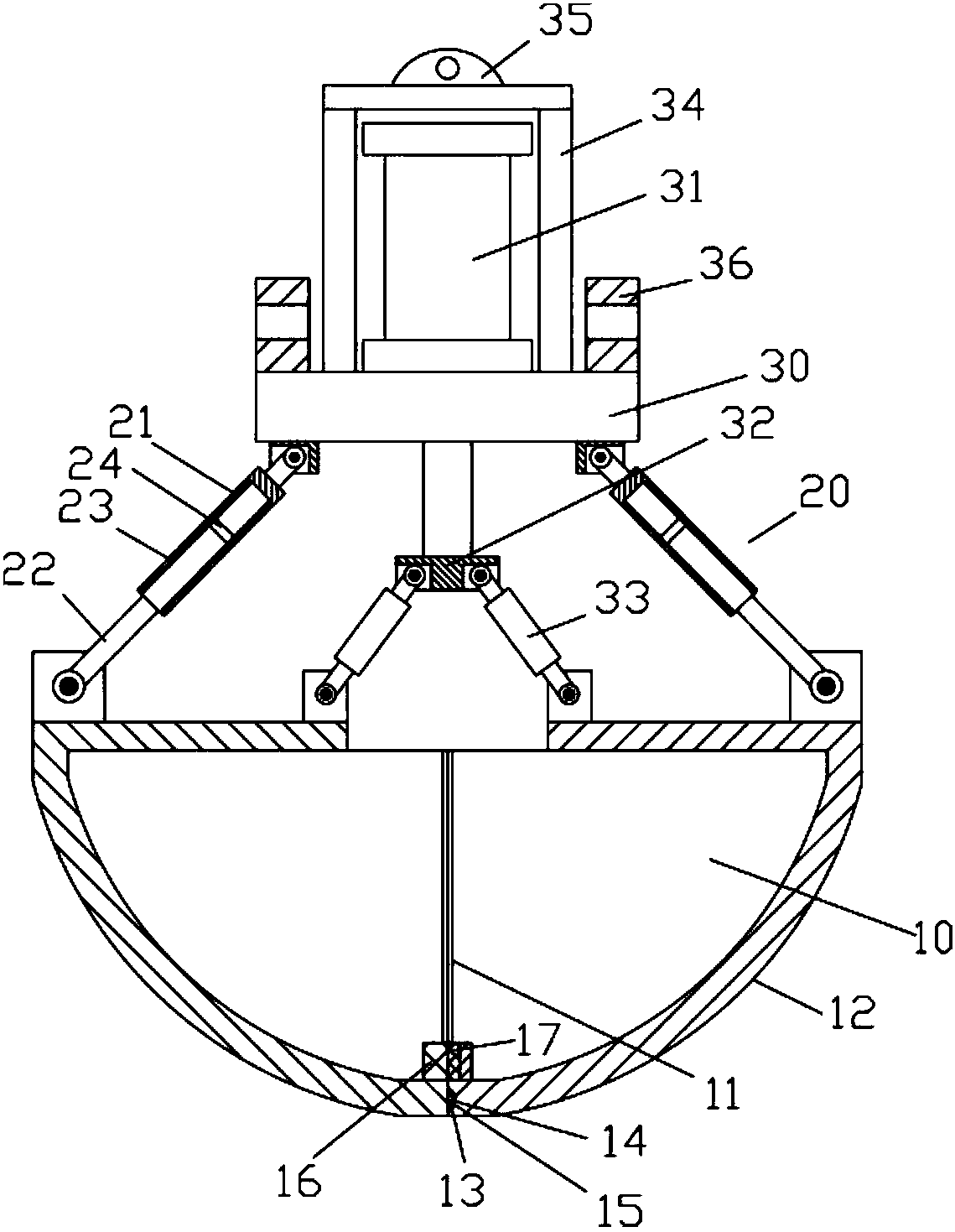
[0017] Examples, see e.g. Figure 1 to Figure 2 As shown, a hydraulic sludge grab includes two oppositely arranged buckets 10 that can be opened and closed. One end of the conveying support rod device 20 is hinged at the rear of the upper top plate of the corresponding bucket 10, and the conveying support The other end of rod device 20 is hinged on the upper connecting block 30, and the middle part top surface of upper connecting block 30 is fixed with pushing oil cylinder 31, and the push rod of pushing oil cylinder 31 passes through upper connecting block 30 and is fixed with pushing block 32 downwards, pushes The rod 33 is at the bottom of the push block 32, the upper ends of the two push rods 33 are respectively hinged at the bottom of both ends of the push block 32, and the other ends of the two push rods 33 are respectively hinged at the front part of the upper top plate of the corresponding bucket part 10 ;

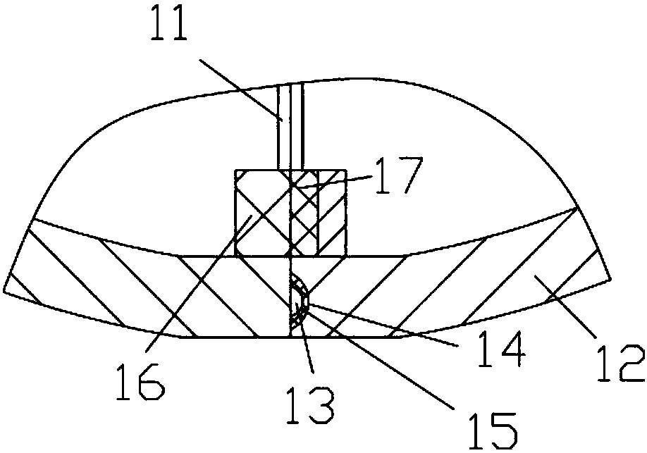
[0018] A buffer layer 11 is fixed on the contacting end surf...


PUM


Abstract

The invention discloses a novel hydraulic sludge grab bucket which comprises two bucket parts which are oppositely arranged and can be opened and closed. One end of each conveying supporting rod device is hinged to the position of the rear portion of an upper top plate of the corresponding bucket part, and the other ends of the conveying supporting rod devices are hinged to an upper connecting block. A push oil cylinder is fixed to the top face of the middle portion of the upper connecting block. A pushing rod of the push oil cylinder penetrates the upper connecting block downwards and is fixedly provided with a push block. Push rods are arranged at the lower portion of the push block. The upper ends of the two push rods are hinged to the bottoms of the two ends of the push block. The other ends of the push rods are hinged to the positions of the front portions of the upper top plates of the bucket parts. The end faces, in contact with each other, of the two bucket parts are fixedly provided with buffering layers, and the two buffering layers abut against each other. The two bucket parts of the novel hydraulic sludge grab bucket are not liable to be impacted and damaged, the protection effect is good, the bucket parts are closed and opened by adopting the single push oil cylinder, the novel hydraulic sludge grab bucket is simple in structure and good in effect, and the two bucket parts can be closed firmly by adopting a permanent magnet block and a permanent magnet layer.

Description

Technical field: [0001] The invention relates to the technical field of sludge treatment, in particular to a hydraulic sludge grab. Background technique: [0002] Existing sludge grabs are generally mechanical or hydraulic. The mechanical structure is complex, troublesome to manufacture, and the effect is not ideal. The hydraulic structure generally uses a hydraulic cylinder directly installed at the rear of the bucket for pushing and pulling. , which requires a plurality of hydraulic cylinders. At the same time, there is generally no buffer mechanism at the end faces where the two buckets of the existing grabs are pressed against, which is easy to be damaged by collision. Invention content: [0003] The purpose of the present invention is to overcome the deficiencies of the prior art and provide a hydraulic sludge grab. Its two buckets are not easy to be damaged by collision, and the protection effect is good. It uses a single push cylinder to realize closing and opening,...

Claims


Application Information

Patent Timeline
Patent Type & Authority Patents(China)
IPC IPC(8): B66C3/16
CPCB66C3/16
Inventor 周东
Owner PULIZI ENVIRONMENT TECH SUZHOU CO LTD
Why Eureka
Try Eureka