Lens barrel

A lens barrel and lens technology, which is applied to instruments, televisions, installations, etc., can solve problems such as complex structures, staggered positions of frame parts, and lens optical axis deviation, and achieve simple and reliable fixing effects

Active Publication Date: 2016-06-08
OM DIGITAL SOLUTIONS CORP
View PDF9 Cites 2 Cited by
  • Summary
  • Abstract
  • Description
  • Claims
  • Application Information

AI Technical Summary

Problems solved by technology

Therefore, at this time, the pressing force in the thrust direction of the countersunk screw is concentrated on a part of the outer peripheral surface of the frame member, and due to the frictional force generated between the tapered surface and the outer peripheral surface of the frame member, the force is component in the circumferential direction, which may cause Staggers the position of the frame parts, so sometimes there is an offset in the optical axis of the lens that has been adjusted
[0007] In addition, the means disclosed in the aforementioned Japanese Patent Application Laid-Open No. 2008-170889 has the following problems: the number of parts increases and the structure tends to be complicated

Method used


Image

  • Lens barrel
  • Lens barrel
  • Lens barrel

Examples


Embodiment Construction

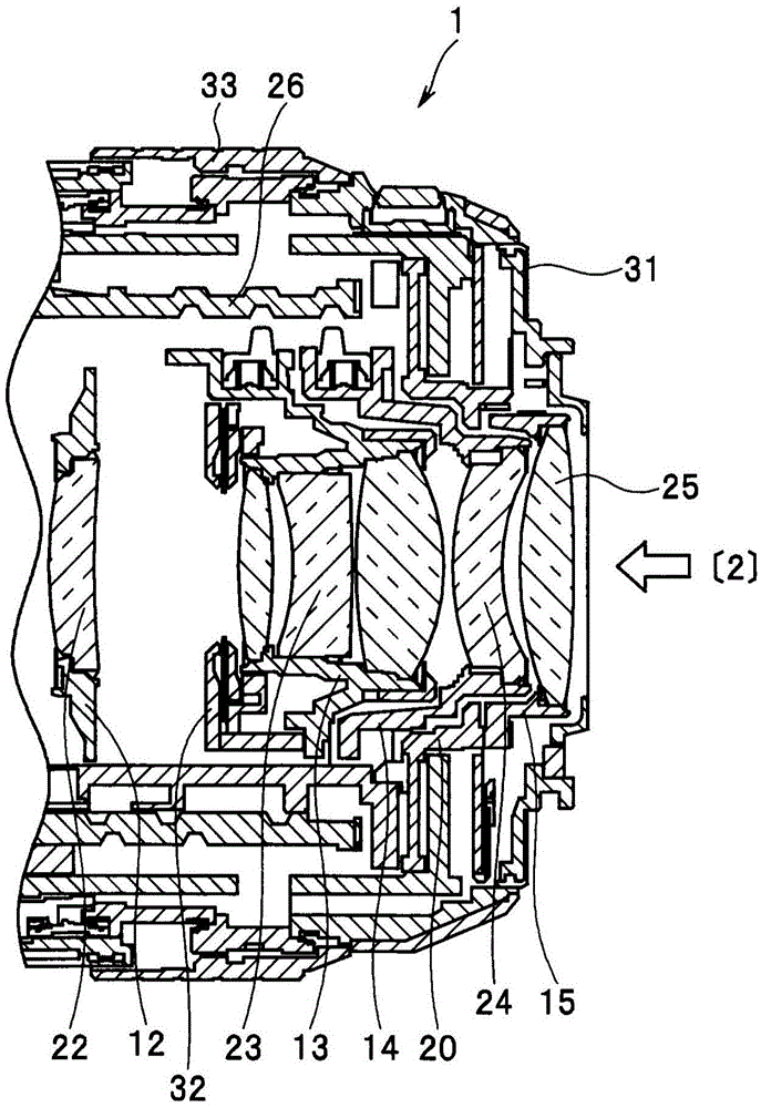
[0019] Hereinafter, the present invention will be described with reference to the illustrated embodiments. One embodiment of the present invention illustrates, for example, a lens barrel used in an imaging device such as a camera (hereinafter simply referred to as a camera) configured to photoelectrically convert an optical image formed by an optical lens using a solid-state imaging device, The image signal thus obtained is converted into digital image data representing a still image or a moving image, the digital data thus generated is recorded in a recording medium, and the still image or moving image is displayed on the basis of the digital image data recorded in the recording medium displayed on the device.

[0020] In addition, in the present embodiment, the optical axis of the imaging optical system in the lens barrel is denoted by a symbol O. And, in the direction along the optical axis O, the side facing the front surface of the lens barrel where the subject exists is...


PUM


Abstract

A lens barrel includes: a first barrel (20); a second barrel (15) that, with respect to the first barrel, is capable of relative movement in a direction orthogonal to the optical axis; an adjustment member (39) for adjusting an amount of the relative movement; two adjustment member housing portions (36a) that are provided in a diametral space between the first barrel and the second barrel, are formed so as to be separate from each other in a circumferential direction and are capable of housing the adjustment member; a plurality of screws (36x); a plurality of fastening portions (36z) for threadedly engaging and fastening the first barrel and the second barrel in parallel with the optical axis by means of the plurality of screws; and one washer member (36) that is held in an integral manner between the plurality of screws and the plurality of fastening portions.

Description

technical field [0001] The present invention is a technical idea related to simplification of the core adjustment (optical axis adjustment) structure of an imaging optical system in a lens barrel and improvement of adjustment accuracy. Background technique [0002] Conventionally, a lens barrel used in an imaging device such as a camera is composed of an imaging optical system composed of a plurality of optical lenses, a plurality of cylindrical or annular frame members, a driving mechanism, and the like. As the plurality of frame members, there is, for example, a lens holding frame configured to hold a plurality of lens groups constituting the imaging optical system and move forward and backward in a direction along the optical axis for focusing and zooming. [0003] In conventional lens barrels, in order to maintain the optical performance of the imaging optical system, after adjusting the decentering of the centers of the optical axes of a plurality of lens groups and per...

Claims


Application Information

Patent Timeline
Patent Type & Authority Applications(China)
IPC IPC(8): G02B7/02H04N5/225
CPCG02B7/023H04N23/55
Inventor 宍户宏行
Owner OM DIGITAL SOLUTIONS CORP
Why Eureka
Try Eureka