Special gear case for labor-saving bicycle and gear transmission mechanism in gear case

A technology of gear transmission mechanism and gearbox, which is applied in the direction of wheel transmission, vehicle gearbox, vehicle parts, etc., and can solve problems such as riding effort

Inactive Publication Date: 2016-06-15
杨锡辉
View PDF0 Cites 2 Cited by
  • Summary
  • Abstract
  • Description
  • Claims
  • Application Information

AI Technical Summary

Problems solved by technology

[0004] The purpose of the present invention is to solve the above-mentioned problems that bicycle riders are struggling to ride in the prior art, and to provide a labor-saving bicycle utilizing the principle of leverage.

Method used


Image

  • Special gear case for labor-saving bicycle and gear transmission mechanism in gear case
  • Special gear case for labor-saving bicycle and gear transmission mechanism in gear case
  • Special gear case for labor-saving bicycle and gear transmission mechanism in gear case

Examples


Embodiment 1

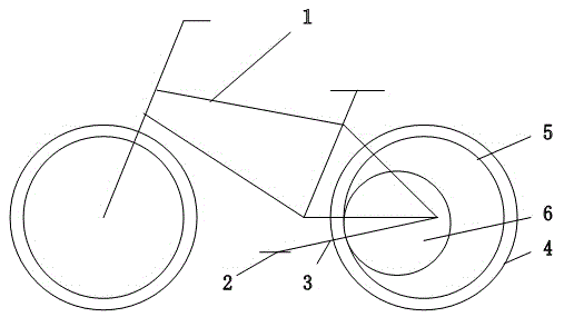
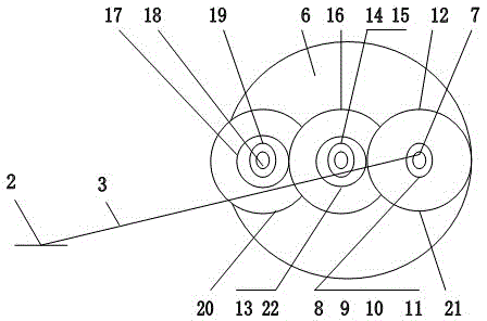
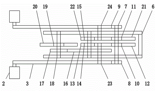
[0007] figure 1 figure 2 image 3 Among them, a special gearbox 6 for a labor-saving bicycle and the gear transmission mechanism in the gearbox include a bicycle 1. A pair of pedals 2 that move up and down are arranged on the left and right sides of the frame, and a gear box 6 is installed in the rear wheel 4 of the bicycle. Connect input shaft 7. : The input shaft 7 that the ball bearing 8 is connected is a fulcrum that does not rotate. The two input bull gears 12, 21 are in turn connected to the input shaft 7 via ball bearings 10, 11. The left and right long arms 3 are fixed with linkage rods 23, 24 near the input shaft 7 ball bearings 8, 9, which are respectively connected to the outer contour edges of the input bull gear 12, 21. It is characterized in that: when the cyclist pedals the left pedal 2, the long arm 3 directly drives the input large gear 12 to rotate counterclockwise in one direction through the linkage rod 23, and the torque force input to the large gear...

Embodiment 2

[0009] figure 1 Figure 4 Figure 5 A special gear box 6 for a labor-saving bicycle and a gear transmission mechanism in the gear box, including a bicycle 1. A pair of pedals 2 that move up and down are arranged on the left and right sides of the frame, and a gear box 6 is installed in the rear wheel 4 of the bicycle. , Bearings 25, 26 are connected to the input shaft 7. The input shaft 7 that unidirectional ratchet, bearing 25,26 are connected is unidirectional, and the large torque force rotates. A single input bull gear 27 is directly connected to the input shaft 7 . When the cyclist pedals the left pedal 2, the long arm 3 directly drives the input large gear 27 through the one-way ratchet, the bearing 25 and the input shaft 7 to rotate counterclockwise in one direction, and the torque of the input large gear 27 is also in the long arm 3 ( Leverage), under the action of is directly magnified several times. The single input bull gear 27 meshes with the single pinion 28...


PUM


Abstract

The invention relates to a special gear case for a labor-saving bicycle and a gear transmission mechanism in the gear case. The bicycle is included. The special gear case for the labor-saving bicycle and the gear transmission mechanism in the gear case are characterized in that a pair of pedals moving up and down are arranged on the left and right sides of a frame, the gear case is arranged in a rear wheel of the bicycle, a gear set in the gear case is used for transmitting power, a main gear provided with a unidirectional ratchet or unidirectional bearing is installed on an output shaft, and the main gear is meshed with inner race teeth positioned on the inner wall of a rear strake of the rear wheel. The pair of pedals moving up and down is arranged on the left and right sides of the frame and connected by a linkage device installed on the bicycle frame, the linkage device is composed of a gear and a rack installed on a long arm, and the rack is meshed to the two sides of the gear. The special gear case for the labor-saving bicycle and the gear transmission mechanism in the gear case have the advantages that the lever principle is fully used, to maximize output torque, so that the riding is easier, more convenient and more labor-saving.

Description

technical field [0001] The invention relates to a gear box for a labor-saving bicycle, in particular to a gear box for a labor-saving bicycle [0002] Gear transmission mechanism. Background technique [0003] At present, as the global energy shortage and emissions intensify, and the environment deteriorates, more and more people feel the importance of energy conservation and emission reduction, but if people drive less, what means of transportation should be used instead? Especially in cities, many people commute to and from get off work relatively short distances. If they can replace cars with bicycles, it can greatly reduce the pressure on urban roads, reduce consumption and reduce emissions. However, the existing bicycles mainly rely on people's legs to drive the bicycle forward, and in a circle of the pedals, only a quarter of the fan is exerted by the legs, and the rest are useless. , so it is very difficult to ride, and the distance is a little longer, such as more t...

Claims


Application Information

Patent Timeline
Patent Type & Authority Applications(China)
IPC IPC(8): B62M11/04
Inventor 杨锡辉
Owner 杨锡辉
Why Eureka
Try Eureka