Imaging system

An imaging system and image technology, applied in the field of imaging systems, can solve problems such as the inability to meet the requirements of the viewer's image resolution, and achieve the effect of improving the resolution

Active Publication Date: 2016-06-15
HUAWEI TECH CO LTD
View PDF4 Cites 6 Cited by
  • Summary
  • Abstract
  • Description
  • Claims
  • Application Information

AI Technical Summary

Problems solved by technology

However, this imaging system still cannot meet the viewer's requirements for image resolution.

Method used


Image

  • Imaging system
  • Imaging system
  • Imaging system

Examples


Embodiment Construction

[0026] The following will clearly and completely describe the technical solutions in the embodiments of the present invention with reference to the drawings in the embodiments of the present invention. Obviously, the described embodiments are part of the embodiments of the present invention, not all of them. Based on the embodiments of the present invention, all other embodiments obtained by persons of ordinary skill in the art without making creative efforts shall fall within the protection scope of the present invention.

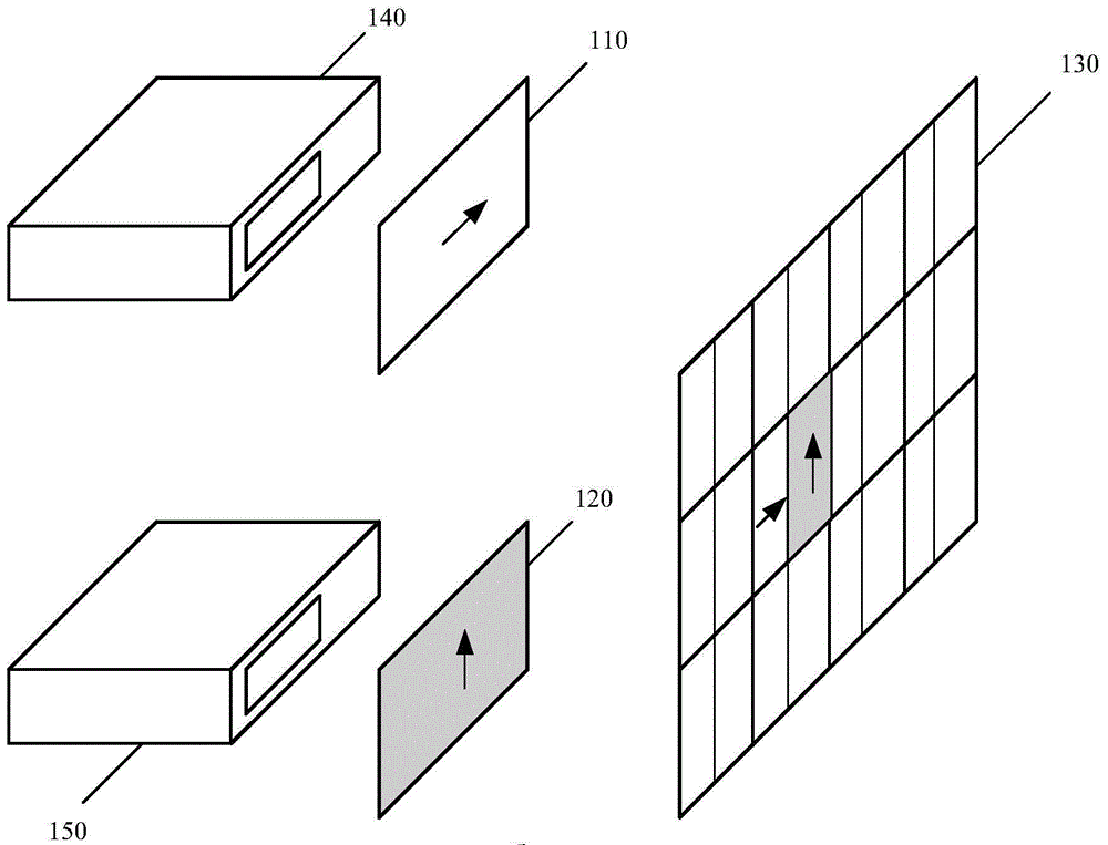
[0027] figure 1 is a schematic diagram of an imaging system according to an embodiment of the present invention. figure 1 The imaging system 100 includes:

[0028] a first polarizing element 110 having a first polarization direction;

[0029] a second polarizing element 120 having a second polarization direction;

[0030] The third polarizing element 130, the first area of ​​the third polarizing element is composed of a first half area and a second half...


PUM


Abstract

The embodiment of the invention provides an imaging system. The imaging system comprises: a first polarization element with a first polarization direction; a second polarization element with a second polarization direction; a third polarization element having a plurality of areas with respect to a plurality of pixel positions, each area in the plurality of areas being formed by a first half area and a second half area, the first half area having the first polarization direction, the second half area having the second polarization direction; a first projection device configured to project images onto a plurality of areas through the first polarization element based on a plurality of pixel positions; and a second projection device configured to project images onto a plurality of areas through the second polarization element based on a plurality of pixel positions. According to the embodiment of the invention, polarization elements are employed to present images from a plurality of views on the areas with respect to the pixel positions, therefore the resolution of imaging may be improved.

Description

technical field [0001] The present invention relates to the field of imaging, and in particular to an imaging system. Background technique [0002] 3D display technology can be divided into two categories: glasses type and naked eye type. Glasses type 3D technology can be subdivided into color difference type, polarized light type and active shutter type, which are commonly referred to as color separation method, light separation method and time division method. Law. Among them, chromatic aberration and polarized 3D technologies are mainly used in projection screens (movies, projectors), and active shutter 3D technologies are used in 3D TVs and 3D movies. [0003] At present, the naked-eye 3D display technologies adopted by various manufacturers mainly include the following types. Light barrier 3D technology, also known as parallax barrier or parallax barrier technology, is similar in principle to polarized 3D. Light barrier 3D products are compatible with existing LCD li...

Claims


Application Information

Patent Timeline
Patent Type & Authority Applications(China)
IPC IPC(8): G02B27/26G03B35/20G03B35/26H04N13/04G02B30/25
CPCG02B30/25H04N13/305H04N13/31G03B35/20G03B35/24G03B35/26G02B30/27
Inventor 柯若莫夫·马克西姆佩车夫·尼克来尼可廷·乌拉迪斯拉夫谢清鹏
Owner HUAWEI TECH CO LTD
Why Eureka
Try Eureka