
A sensing device for testing the weight of contents in a washing bucket of a washing machine

A sensor device, washing machine technology, applied in washing devices, other washing machines, textiles and papermaking, etc., can solve the problems of large installation space and easy collision, to ensure test accuracy and reliability, avoid The effect of vibration, collision and friction

Active Publication Date: 2016-06-22
HANGZHOU KAMBAYASHI ELECTRONICS
View PDF5 Cites 5 Cited by
  • Summary
  • Abstract
  • Description
  • Claims
  • Application Information

AI Technical Summary

Problems solved by technology

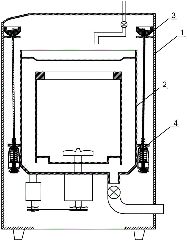
[0003] The present invention aims to solve the problem that the iron core of the sensing device and the inductance coil of the prior art weight sensing device for washing machine are likely to collide when the washing machine is dehydrating, and the installation of the sensing device occupies a large space. Therefore, a solution of the present invention is provided. A sensing device for testing the weight of the contents in the washing bucket of a washing machine. The sensing device of the present invention has good stability when used, and the iron core and the inductance coil will not collide when the washing machine is dehydrated, and the installation space is reasonable

Method used


Image

  • A sensing device for testing the weight of contents in a washing bucket of a washing machine
  • A sensing device for testing the weight of contents in a washing bucket of a washing machine
  • A sensing device for testing the weight of contents in a washing bucket of a washing machine

Examples


Embodiment 1

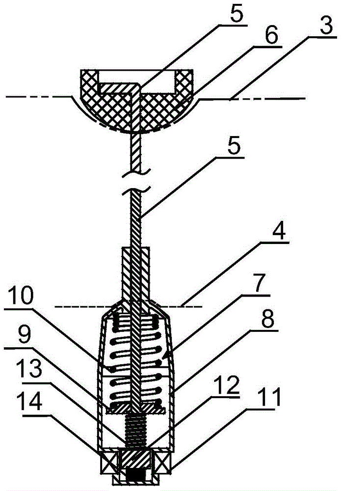
[0018] The sensing device of the present invention, such as figure 1 , figure 2 As shown, a hook A3 is connected to each of the upper four corners of the inner wall of the washing machine outer box 1, and four hooks B4 are connected to the lower part of the outer wall of the washing machine washing tub 2 at circumferential intervals. A hanger rod 5 is hung on it and is stabilized by a pad 6, and a shock absorber 7 is hung on the hook B. The shock absorber has a casing 8, and the lower end of the hanger rod 5 extends into the casing of the shock absorber. A support body 9 is arranged in the shell, the lower end of the boom is connected with the support body, a shock absorbing spring 10 is arranged between the top of the shell and the support body, and the upper part of the shell is hung on the hook B so that the shock absorber is connected to the hook B, A spring A14 is arranged at the bottom of the casing, a magnetic iron core 12 is placed on top of the upper end of the spri...

Embodiment 2

[0021] In this example, the sensing device, such as Figure 4 As shown, the shock-absorbing spring is composed of shock-absorbing spring A10-1 and shock-absorbing spring B10-2 coaxially interlocked. The height of shock-absorbing spring B is smaller than that of shock-absorbing spring A. In the initial state, one end of shock-absorbing spring B is Keep it in the air (when the lower end of the shock absorber spring B is against the support, the upper end remains in the air). The other structures are the same as the implementation one.

[0022] When water is added into the washing tub, as in the first embodiment, the casing of the shock absorber moves downward, and the shock absorber spring A is compressed first. Continue to add water, the shock spring B is compressed. Suppose the elastic coefficient of damping spring A is K1, the free length is La, the elastic coefficient of damping spring B is K4, the free length is Lb, the total stroke of the washing tub is L, and when the d...

Embodiment 3

[0024] In this example, the sensing device, such as Image 6 As shown, what is different from Example 2 is that the support body 9 is provided with a cavity that opens downward, and the cavity is provided with a guide rod 15, the lower end of the guide rod is connected to the magnetic iron core 12, and the connection between the guide rod and the magnetic iron core has a diameter The length of the guide rod is to keep the upper end of the guide rod away from the top of the cavity, the spring B13 is sleeved on the guide rod, the lower end of the spring B is placed on the step of the guide rod, and the upper end of the spring B is higher than the guide rod. top of the rod. The other structures are the same as the second implementation. In this example, while maintaining the structure and function of the spring B, the distance between the magnetic iron core and the support body can be reduced, which is beneficial to the miniaturization of the sensing device.


PUM


Abstract

The invention provides a sensing device for testing the weight of contents in a washing bucket of a washing machine, which realizes stable and accurate detection. The sensing device comprises hanging hooks A connected to upper portion corners of the inner wall of an outer tank body of a washing machine and hanging hooks B connected to the lower portion of the outer wall of a washing bucket of the washing machine; the hanging hooks B and the hanging hooks A correspond to each other longitudinally; a lifting rod is hung on and connected to each hanging hook A; each hanging hook B is connected with a shock absorber via the hanging and connection of an outer shell of the shock absorber; the lower end of each lifting rod extends into the outer shell of the corresponding shock absorber; a support body is arranged in each outer shell; the lower end of each lifting rod is connected with the corresponding support body; a shock absorption spring is arranged between each support body and the upper top of the corresponding outer shell; the bottom of each outer shell is provided with a spring A and the upper end of the spring A is pressed against a magnetic iron core; a spring B is pressed against each magnetic iron core and the corresponding support body therebetween; the periphery of the lower portion of each outer shell, corresponding to the matching magnetic iron core, is fixedly sleeved with an inductance coil; the elastic coefficient of the springs A and the elastic coefficient of the springs B are not equal. The sensing device is used for detection of the weight of contents in a washing bucket of a washing machine.

Description

technical field [0001] The invention relates to a sensing device for a washing machine, in particular to a sensing device for testing the weight of contents in a washing tub of a washing machine. Background technique [0002] The washing machine needs to sense the weight of the washing load when washing, and the amount of water entering when the water is in action. At present, the motor is generally used to give the initial rotation action to drive the washing load to rotate, and the weight of the washing load can be vaguely judged by detecting the time when the pulsator stops after the motor stops. This method has low measurement accuracy, which may lead to misjudgment, waste of washing water resources or unclean washing. Japanese Patent Laid-Open No. 2001-120885 discloses a weight sensing device for a washing machine. A weight sensor is set on the boom between the washing machine box and the outer tub, and the deformation of the compression spring is converted into induct...

Claims


Application Information

Patent Timeline
Patent Type & Authority Applications(China)
IPC IPC(8): D06F39/00D06F37/20
Inventor 竺建军邓睿
Owner HANGZHOU KAMBAYASHI ELECTRONICS
Learn More