Control method for throttling freezing type cryosurgery device

A control method and surgical technology, applied in the field of medical devices for cryosurgical treatment, can solve the problems of low-temperature working medium waste in gas throttling cryosurgical equipment, and achieve the effects of improving gas utilization, reducing costs, and increasing hyperthermia

Inactive Publication Date: 2016-06-29
赵国江
View PDF11 Cites 4 Cited by
  • Summary
  • Abstract
  • Description
  • Claims
  • Application Information

AI Technical Summary

Problems solved by technology

[0011] Aiming at the above-mentioned prior art, the present invention provides a control method of a throttling cryosurgical device, which solves the huge waste of low-temperature working medium in gas throttling cryosurgical equipment, and the use of two different throttling properties for freezing and rewarming...

Method used


Image

  • Control method for throttling freezing type cryosurgery device
  • Control method for throttling freezing type cryosurgery device
  • Control method for throttling freezing type cryosurgery device

Examples


Embodiment 1

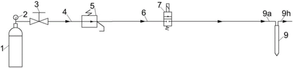
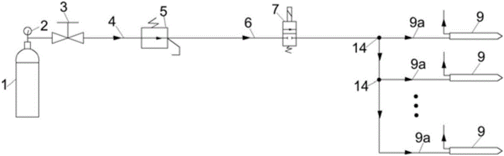
[0037] Embodiment 1: as figure 1 As shown, the structure of the throttling refrigeration type cryosurgical device used is: comprising a refrigeration gas circuit and a refrigerator 9, the refrigeration gas circuit includes a gas inlet pipe 4 connected in sequence with the gas outlet of the high-pressure gas source 1 and the refrigeration gas main pipe 6. The gas input pipe 4 is provided with a barometer 2 and a gas source pressure regulating valve 3, and the gas source pressure regulating valve 3 of the present invention is opened and closed manually or electrically. A pressure-limiting valve 5 is provided at the connection between the gas input pipe 4 and the refrigerated gas main pipe 6 , and a refrigerated solenoid valve 7 is provided on the refrigerated gas main pipe 6 . Such as image 3 As shown, multiple refrigerator inlet pipes 9a can also be connected to the end of the frozen gas main pipe 6 through the second tee 14 connected in series, and one refrigerator is connec...

Embodiment 2

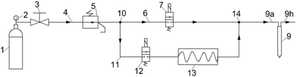
[0040] Embodiment 2: as figure 2 As shown, a kind of embodiment that can preheat the gas, the structure of the throttling refrigeration type cryosurgical device used is: including the freezing gas circuit, the heating gas circuit 11 and the freezer 9, and the said freezing gas circuit includes the high-pressure gas source 1 The gas inlet pipe 4 connected with the gas outlet in sequence and the refrigerated gas main pipe 6, the gas input pipe 4 is provided with a barometer 2 and a gas source pressure regulating valve 3, the gas input pipe 4 and the refrigerated gas main pipe 6 A pressure limiting valve 5 is provided at the joint of the refrigerated gas main pipe 6, and a refrigerated solenoid valve 7 is provided on the refrigerated gas main pipe 6, and a first Tee 10, a second tee 14 is provided at the connection between the frozen gas main pipe 6 and the refrigerator inlet pipe 9a, and is connected to the refrigerator; the heating gas circuit 11 is connected to the first thre...


PUM


Abstract

The invention discloses a control method of a throttling freezing type cryosurgical device, which comprises a freezing air path, a heating air path and a throttling type refrigerator. The freezing air path is a high-pressure gas source, a gas input pipe, a pressure limiting It is composed of a gas main pipe, a refrigeration solenoid valve and a refrigerator inlet pipe, and a heating solenoid valve and a gas heater are arranged on the heating gas path. When the high-pressure air source is turned on and the freezing solenoid valve is turned on, the high-pressure gas realizes throttling freezing of the freezer; when the high-pressure gas source is turned off and the freezing solenoid valve is turned on, the gas discharged from the pipeline undergoes heat exchange with the frozen tissue in the freezer, generating Rewarming effect; the heating effect can be achieved when the high pressure air source is turned off, the freezing solenoid valve is closed and the heating solenoid valve and gas heater are turned on. The invention corrects the technical prejudice that throttling refrigerating gas can only be used for freezing, solves the waste of low-temperature working medium and the problem of rewarming in gas throttling cryosurgical equipment, and realizes three functions of freezing, rewarming and heating.

Description

technical field [0001] The invention relates to a medical instrument for cryosurgical treatment, which is characterized in that it realizes freezing through the throttling effect of high-pressure gas and realizes rewarming and heating functions through evacuating the gas in the device. Background technique [0002] Cryosurgery is a method of using ultra-low temperature to damage and ablate diseased tissue, and it is also the earliest diseased tissue ablation technique used in human history. Since American neurosurgeon Irving Cooper and engineer Arnold Lee invented the probe-shaped liquid nitrogen freezer and used it to freeze brain tissue in 1960, liquid nitrogen was used as a low-temperature working medium (refrigerant), and heated nitrogen was used as a liquid for high-temperature working medium (heat medium). Nitrogen cryosurgery equipment is used to treat various tumors. However, the complex and cumbersome liquid nitrogen freezing equipment, difficult operation and poor...

Claims


Application Information

Patent Timeline
IPC IPC(8): A61B18/02
CPCA61B18/02A61B2018/00017A61B2018/00964A61B2018/0231A61B2018/0262
Inventor 赵国江李萍董元勃
Owner 赵国江
Why Eureka
Try Eureka