Printer guide direction adjusting device

A technology for guide adjustment and printing machines, applied in printing machines, rotary printing machines, printing, etc., can solve problems such as difficult to achieve fine-tuning, large human errors, and tediousness, and achieve the effect of simplifying the degree of complexity and solving the problem of low accuracy

Active Publication Date: 2016-06-29
SHANGHAI CHANGYUAN ELECTRONICS MATERIAL +1
View PDF4 Cites 1 Cited by
  • Summary
  • Abstract
  • Description
  • Claims
  • Application Information

AI Technical Summary

Problems solved by technology

This method is cumbersome, and at the same time introduces a large human error, and it is difficult to fine-tune manually, so improving the guide frame has become a demand

Method used


Image

  • Printer guide direction adjusting device
  • Printer guide direction adjusting device

Examples


Embodiment Construction

[0019] In order to more clearly illustrate the embodiments of the present invention or the technical solutions in the prior art, the present invention will be specifically described below in conjunction with the accompanying drawings and embodiments. The drawings in the following description are only some embodiments of the invention. For those skilled in the art, other drawings can also be obtained based on these drawings without creative effort.

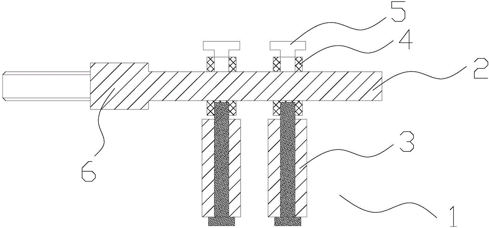
[0020] Such as figure 1 Shown is the schematic diagram before the improvement of the guide adjustment device 1 of the printing machine in the present invention, including the fixed shaft 2, the guide wheel 3, the guide wheel moving sleeve 4 and the fastening screw 5, wherein the guide wheel moving sleeve 4 is perpendicular to the axial direction of the fixed shaft 2 Set on the fixed shaft 2, one end of the guide wheel 3 is sleeved on one end of the guide wheel moving sleeve 4, and the other end of the guide wheel moving sleeve 4 i...


PUM


Abstract

The invention relates to the field of machinery, in particular to a guide direction adjusting bracket for printing on a finished product, and discloses a printer guide direction adjusting device which comprises a fixing shaft, guide wheels, guide wheel moving sleeves and an adjusting lead screw, wherein an open pore is formed in one end of the fixing shaft; the adjusting lead screw is arranged in the open pore; the guide wheel moving sleeves are arranged on the adjusting lead screw along the direction perpendicular to the axial direction of the fixing shaft; and the guide wheels are sleeved by the guide wheel moving sleeves along the direction parallel to the axial directions of the guide wheel moving sleeves. By adoption of the printer guide direction adjusting device, the defect that in the prior art, the guide wheels cannot be highly precisely adjusted by fastening screws is overcome; and meanwhile, the adjusting complexity is simplified.

Description

technical field [0001] The invention relates to the field of machinery, in particular to a guide adjustment device for printed characters on finished products. Background technique [0002] Such as figure 1 Shown is the guide adjustment bracket currently used for printing on the finished heat-shrinkable tube. When it is necessary to print on the heat-shrinkable tube, the figure 1 Only when the guide wheel in the guide wheel is aligned with the center of the character wheel can the characters be printed, and at the same time keep it in the center position. In this process, the adjustment of the position of the guide wheel relative to the fixed shaft needs to loosen the fastening screws on the moving sleeve of the guide wheel, and manually align the position to be printed with the center of the printing wheel. This method is cumbersome, and at the same time introduces a large human error, and it is difficult to fine-tune manually, so it has become a demand to improve the gui...

Claims


Application Information

Patent Timeline
Patent Type & Authority Applications(China)
IPC IPC(8): B41F17/10
Inventor 翁妙峰
Owner SHANGHAI CHANGYUAN ELECTRONICS MATERIAL
Why Eureka
Try Eureka