
Anti-backward motion device of car

A rear-prevention and automobile technology, which is applied to vehicle components, transportation and packaging, brakes, etc., can solve problems such as car slipping accidents, vehicle damage, car crashes, etc., and achieve the effect of preventing back slipping

Inactive Publication Date: 2016-06-29
NANCHANG INST OF TECH
View PDF11 Cites 4 Cited by
  • Summary
  • Abstract
  • Description
  • Claims
  • Application Information

AI Technical Summary

Problems solved by technology

Many people in the process of parking and starting on the ramp, if they are not careful, there will often be car slipping accidents, which may cause partial damage to the vehicle, or even cause death.

Method used


Image

  • Anti-backward motion device of car
  • Anti-backward motion device of car
  • Anti-backward motion device of car

Examples


Embodiment 1

[0024] Embodiment 1: see Figure 1-5 .

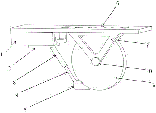
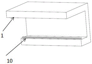
[0025] An automobile anti-rollback device, which includes a frame connection part and a telescopic thrust part, the frame connection part is a main frame 1 with a bottom opening, and the telescopic thrust part includes a sliding connection with the opening end of the main frame 1 The slider 2, the first drive mechanism that drives the slider 2 to move horizontally, the stopper that moves integrally with the slider 2, and the second drive mechanism that drives the retraction of the stopper, drives the second drive mechanism a first rotating mechanism for rotating and a second rotating mechanism for driving the stop block to rotate;

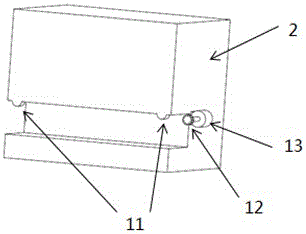
[0026] Described first driving mechanism comprises roller 11, first stepper motor 13 and first gear 12, and described slide block 2 is provided with a chute, and roller 11 is housed on the inner sidewall of chute opening, and one side of chute A first stepping motor 13 is provided, the output end of the fi...

Embodiment 2

[0032] Example 2, see Figure 1-7 , including vehicle frame 6, suspension suspension 7, vehicle axle 8, wheel 9, main frame 1 and vehicle frame are fixedly connected by bolts, when the car is on a ramp to stop and start, the driver turns on the control switch of the device in the cab, When the first stepper motor 13 drives the gear 12 to move on the rack 10 so as to drive the slider 2 to slide to the limit tooth position at one end of the rack 10 to the rear of the frame, the second stepper motor 14 drives the drive gear 16 to move Rotation, of course, stepper motors can also achieve this function, because stepper motors can precisely control the number of turns or strokes of rotation. Because the driving gear 16 is fixedly connected with the hydraulic cylinder 15 at the top of the primary hydraulic rod 3 and the top, so the driving gear 16 rotates, and the hydraulic rod 3 also rotates to a certain angle. After the driving gear stops rotating, the hydraulic cylinder 15 begins...


PUM


Abstract

The invention discloses an anti-backward motion device of cars. The anti-backward motion device comprises a frame connection portion and a stretching anti-thrust portion, wherein the frame connection portion is a main body frame with a lower opening, the extension anti-thrust portion comprises a slide block, a first drive mechanism, a stop block, a second drive mechanism, a first rotating mechanism and a second rotating mechanism, the slide block is connected with an opening end of the main body frame in a sliding manner, the first drive mechanism drives the slide block to move horizontally, the stop block moves together with the slide block, the second drive mechanism drives the stop block to stretch, the first rotating mechanism drives the second drive mechanism to rotate, and the second rotating mechanism drives the stop block to rotate. The anti-backward motion device is improved on the basis of the original frame of the car, the motor can be powered by an operator through an operation switch, the motor can drive a hydraulic lever to swing up and down for a given angle to extend out a secondary hydraulic lever, and the position of a wedge block on the front section can be adjusted by virtue of a stepper motor on the wedge block, so that the car is at a parking safety state, and the backward motion of the car when the car is stopped and started on a ramp can be effectively prevented.

Description

technical field [0001] The invention belongs to the technical field of vehicle braking, and in particular relates to an automobile anti-rollback device. Background technique [0002] With the development of my country's social economy and the improvement of traffic roads, the transportation capacity of highways has been greatly improved, and the supply and demand relationship in the transportation market has undergone major changes. The development of the national economy and the daily life of the people are increasingly inseparable from trucks. transportation. At present, the freight market is developing in the direction of large-scale and heavy-duty, followed by a sharp increase in traffic accidents of large trucks, which has brought great losses to people's lives and property. One type of accident is the driver It is caused by the driving level of the truck and the defects of the truck braking system itself. Many people in the process of parking and starting on the ramp,...

Claims


Application Information

Patent Timeline
IPC IPC(8): B60T3/00
CPCB60T3/00
Inventor 寇桂岳杨艳艳林谋有甘志梅杨军平初长宝李志春余鑫周志斌余创先
Owner NANCHANG INST OF TECH
Learn More