SMT laser template polishing clamp

A technology of polishing fixtures and laser templates, applied in the direction of electrolytic components, electrolytic process, etc., can solve the problems of time waste and cost increase, and achieve the effect of convenient polishing work

Inactive Publication Date: 2016-06-29
中山市创隆电子有限公司
View PDF4 Cites 6 Cited by
  • Summary
  • Abstract
  • Description
  • Claims
  • Application Information

AI Technical Summary

Problems solved by technology

[0005] The existing technology realizes the automatic clamping of the SMT laser template through the gear system, which saves the time waste caused by manual participation and improves work efficiency. However, this solution is to tightly attach the SMT laser template to the fixture plate, so that The lower end surface of the SMT laser template is in a non-exposed state. If the lower end surface of the SMT laser template needs to be polished later, then the SMT laser template should be turned over again, which will cause a waste of time and increase the cost.

Method used


Image

  • SMT laser template polishing clamp
  • SMT laser template polishing clamp
  • SMT laser template polishing clamp

Examples


Embodiment Construction

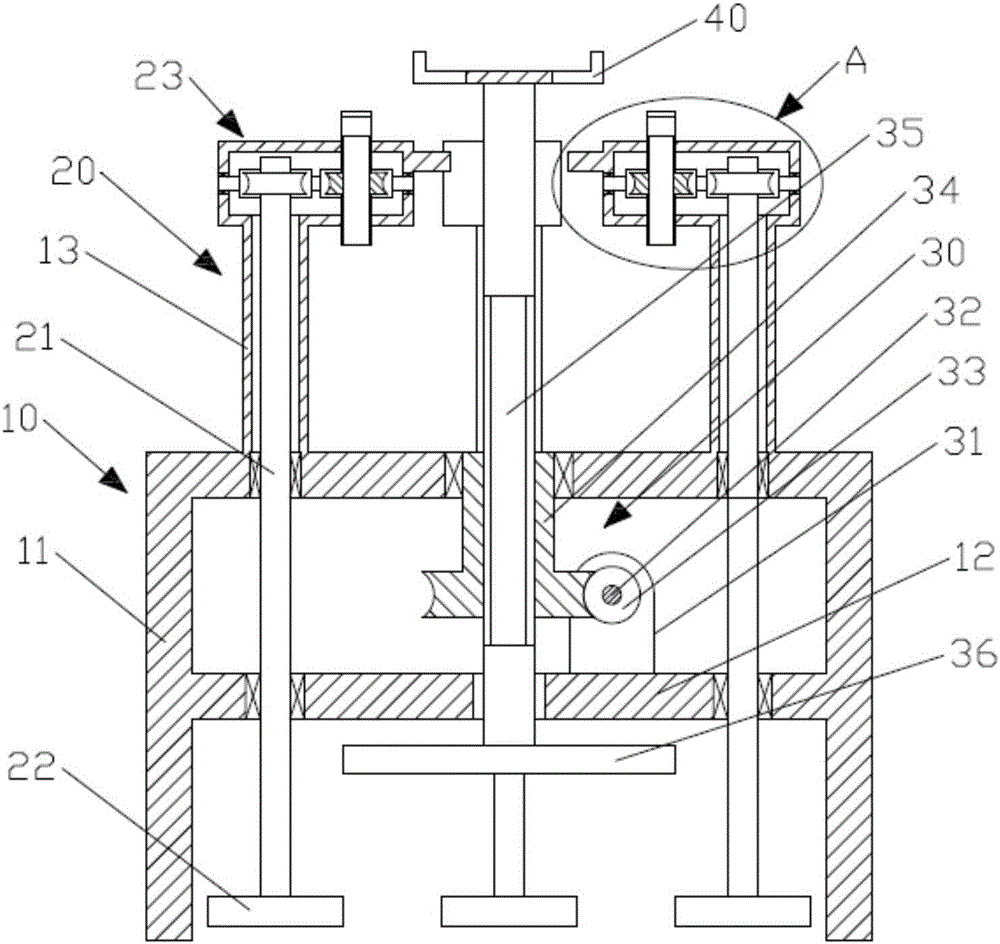
[0022] like figure 1 As shown, a kind of SMT laser template polishing fixture, comprises frame 10, clamping device 20, template lifting device 30; Plate 12; four hollow columns 13 are vertically fixed on the upper end surface of the frame 10; the through holes inside the hollow columns 13 communicate with the empty cavity inside the frame 10;

[0023] like figure 1 As shown, the template lifting device 30 includes a first worm 33, a central transmission block 34, a first threaded rod 35 and a central gear 36; a pair of support seats 31 are vertically fixed on the upper end surface of the fixed plate 12; the first worm 33 passes through the central shaft 32 is longitudinally pivoted on the support seat 31; the upper part of the central transmission block 34 is a cylinder and the lower part is a worm wheel; the central transmission block 34 is formed with a threaded hole penetrating from top to bottom; the upper part of the central transmission block 34 is pivotally connected t...


PUM


Abstract

The invention discloses an SMT laser template polishing clamp. The SMT laser template polishing clamp comprises a rack, clamping devices and a template lifting device. A vacant cavity is formed in the rack. A fixing plate is transversely arranged in the rack. Four hollow columns are vertically fixed to the upper end face of the rack. Through holes in the hollow columns communicate with the vacant cavity in the rack. The template lifting device is vertically arranged in the center position of the rack. The number of the clamping devices is the same as the number of the hollow columns. The clamping devices are fixed to the hollow columns. A template containing box is fixed to the upper portion of a first threaded rod of the template lifting device, and a center gear is fixed to the lower portion of the first threaded rod of the template lifting device. Transmission shafts of the clamping devices are vertically inserted in the hollow columns. The middle portions of the transmission shafts are pivoted to the upper side wall of the rack, and transmission gears are fixed to the upper portion and the lower portion of the fixing plate. The SMT laser template polishing clamp has the beneficial effects that by means of the template lifting device and the clamping devices, a template can be suspended above the rack, and the subsequent polishing work is greatly facilitated.

Description

technical field [0001] The invention relates to the technical field of SMT laser templates, in particular to an SMT laser template polishing fixture. Background technique [0002] In the process of SMT laser stencil production, when the stainless steel sheet is laser cut, there will be burrs and oxides on the hole wall, which will seriously affect the quality of SMT laser stencil printing solder paste and cannot meet customer requirements. In order to solve this problem, the hole wall of the steel sheet after laser cutting must be processed. The treatment method is electrochemical polishing process. In order to perform electrochemical polishing, a polishing jig must be used, and the laser-cut steel sheet must be mounted on the polishing jig, so that it can cooperate with the polishing equipment to complete the electrochemical polishing. [0003] In the existing SMT laser template manufacturing process, the fixture is usually fixed by screws. The disadvantage is that an add...

Claims


Application Information

Patent Timeline
Patent Type & Authority Applications(China)
IPC IPC(8): C25F7/00C25F3/24
CPCC25F3/24C25F7/00
Inventor 董芬芳
Owner 中山市创隆电子有限公司
Why Eureka
Try Eureka