Rotary adjusting device of energy saving lamp

A technology of rotary adjustment, energy-saving lamps, applied in lighting devices, lighting auxiliary devices, fixed lighting devices, etc., can solve the problems of limited effect, inability to adjust, and inability to adjust the illumination angle.

Active Publication Date: 2016-06-29
SHENZHEN PURPLE LIGHTING TECH
View PDF7 Cites 6 Cited by
  • Summary
  • Abstract
  • Description
  • Claims
  • Application Information

AI Technical Summary

Problems solved by technology

[0002] Existing LED atmosphere lights are generally fixed in the lamps, and the lamps are generally fixed, and their irradi

Method used


Image

  • Rotary adjusting device of energy saving lamp
  • Rotary adjusting device of energy saving lamp

Examples


Embodiment

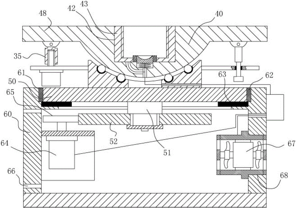
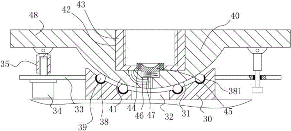
[0016] Example: see Figure 1 to Figure 2 As shown, a rotary adjustment device for an energy-saving lamp includes a lamp connection base 30, a spherical groove 31 is provided in the middle of the top surface of the lamp connection base 30, an axial threading through hole 32 is provided in the middle of the bottom surface of the spherical groove 31, and the connecting seat The bottom surface of the middle part of 40 has a spherical protrusion 41, and the spherical protrusion 41 is inserted and sleeved in the spherical groove 31. A plurality of spherical concave holes 38 are evenly distributed on the wall surface of the spherical concave hole 31, and the wall surface of the spherical concave hole 38 is fixed. The grinding layer 381 is nested with a sliding ball 39 in the spherical concave hole 38, the sliding ball 39 is pressed against the wear-resistant layer 381, and the spherical protrusion 41 is pressed against the sliding ball 39;

[0017] The bottom surface of the connecti...


PUM


Abstract

The invention discloses a rotary adjusting device of an energy saving lamp. The rotary adjusting device comprises a lamp connecting base; a spherical surface groove is formed in the middle part of the top surface of the lamp connecting base; an axial wire penetrating through hole is formed in the middle part of the bottom surface of the spherical surface groove; a spherical surface projection is arranged on the bottom surface of the middle part of a connecting base, and is inserted in the spherical surface groove; multiple spherical surface concave holes are uniformly distributed in the wall surface of the spherical surface groove; wear resistant layers are fixed on the wall surfaces of the spherical surface concave holes; slide balls are embedded in the spherical surface concave holes, and are pressed against the wear resistant layers; the spherical surface projection is pressed against the slide balls; the bottom surface of the connecting base is fixed on a turntable; a rotating shaft is fixed at the middle part of the bottom surface of the turntable; a rotating gear is fixed at the lower end of the rotating shaft; a bottom connecting box is fixed on the ground below the connecting base; and a rotating through hole is formed in the middle part of a top plate of the bottom connecting box. After an LED lamp is mounted on the rotary adjusting device, an irradiating angle of the LED lamp can be adjusted through operations of an inclined adjusting motor and a rotating motor to satisfy different irradiating requirements.

Description

Technical field: [0001] The invention relates to the technical field of energy-saving lamps, in particular to an energy-saving lamp rotary adjustment device. Background technique: [0002] Existing LED atmosphere lamps are generally fixed in lamps, and the lamps are generally fixed, and their irradiation angle cannot be adjusted, so that they cannot be adjusted according to the needs of users, and the effect is limited. Invention content: [0003] The purpose of the present invention is to address the deficiencies of the prior art, and provide a rotary adjustment device for energy-saving lamps, after the LED lamp is installed on it, the irradiation angle of the LED lamp can be adjusted through the operation of the tilting adjustment motor and the rotating motor to meet different requirements. Exposure requirements. [0004] Technical solutions of the present invention are as follows: [0005] A rotary adjustment device for an energy-saving lamp, comprising a lamp connect...

Claims


Application Information

Patent Timeline
IPC IPC(8): F21S8/00F21V21/30F21V21/15F21Y115/10
CPCF21S8/00F21V21/15F21V21/30
Inventor 付淑珍
Owner SHENZHEN PURPLE LIGHTING TECH
Why Eureka
Try Eureka