Battery core module

A cell module, a pair of technology, applied in the direction of battery pack parts, batteries, circuits, etc., can solve the problem of poor compression resistance of the end plate, so as to avoid the weak mechanical properties of the middle, enhance the compression resistance, reduce The effect of energy consumption

Active Publication Date: 2016-07-06
CONTEMPORARY AMPEREX TECH CO
View PDF12 Cites 6 Cited by
  • Summary
  • Abstract
  • Description
  • Claims
  • Application Information

AI Technical Summary

Problems solved by technology

[0003] In addition, the fixing of the existing end plate on the base plate usually adopts an additional sleeve member. The sleeve member is provided with through holes and fixed on the base plate by bolts, while the end plate is welded and fixed on the sleeve member, thereby being jointly fixed on the base plate. On the other hand, the mechanical weakness caused by the unavoidable multi-component connection makes the end plate fixed on the base plate not strong in compression

Method used


Image

  • Battery core module
  • Battery core module
  • Battery core module

Examples


Embodiment Construction

[0047] In order to make the purpose, technical solution and advantages of the application clearer, the technical solution of the application will be clearly and completely described below in conjunction with the embodiments of the application and the accompanying drawings. Obviously, the described embodiments are part of the embodiments of the application , but not all examples. All other embodiments obtained by those skilled in the art on the basis of the technical solutions and given embodiments provided in this application without creative efforts shall fall within the scope of protection of this application.

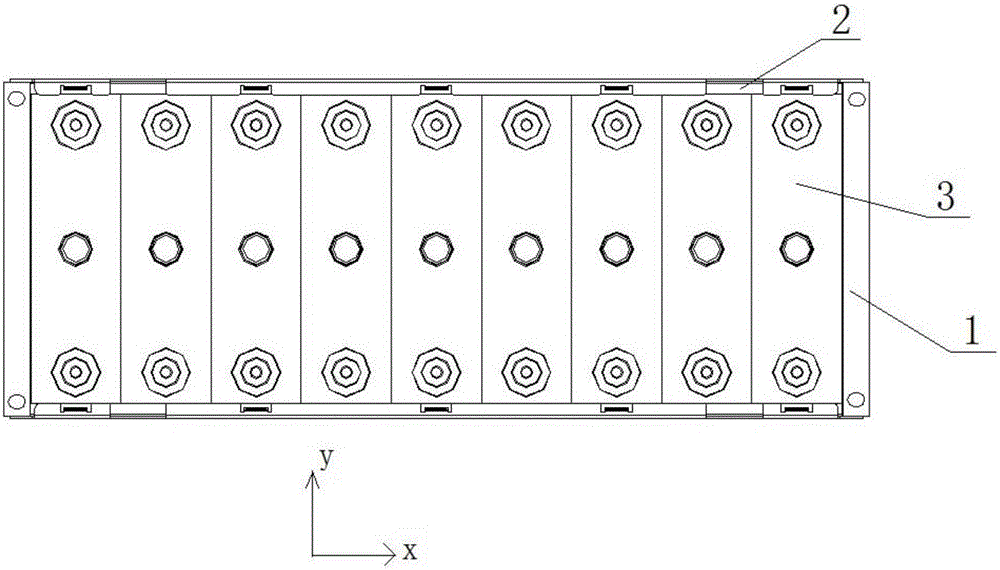
[0048] The "length", "width" and "height" in the text are all referred to the placement state of the battery cell 3 (battery unit) in the drawings.

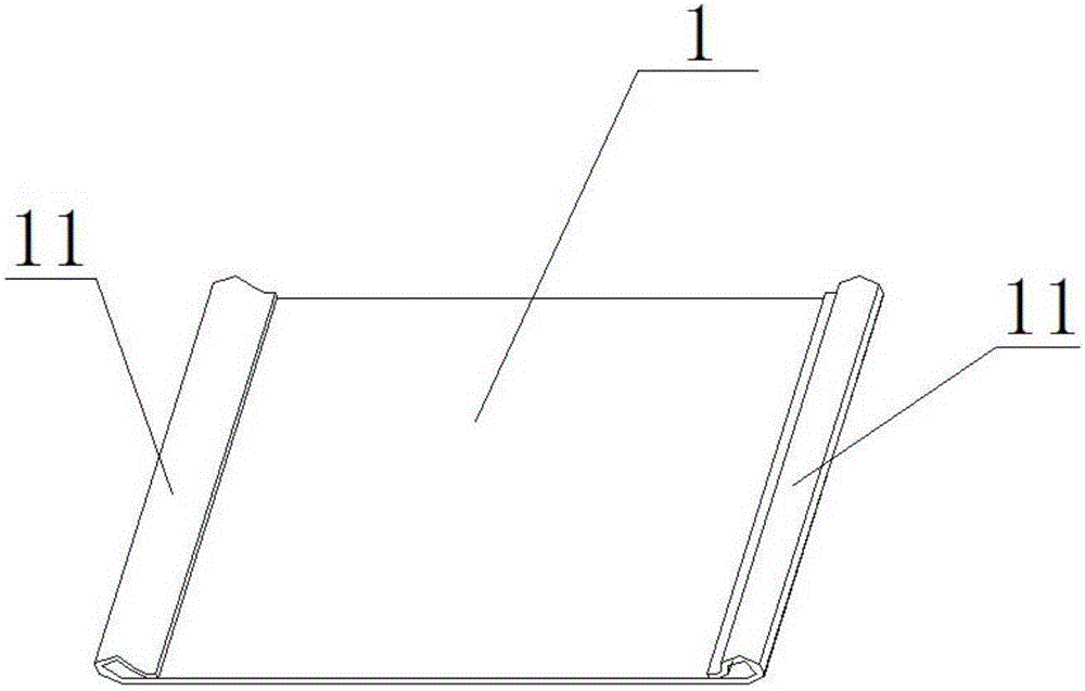
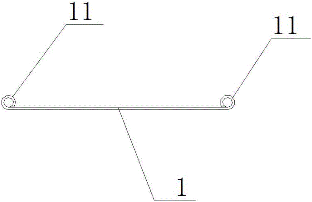
[0049] A cell module, such as figure 1 As shown, it includes a base plate (at the bottom of the electric core 3, not shown), a plurality of electric cores 3, a pair of end plates 1, a pair of side plates 2 and a plural...


PUM


Abstract

The application relates to the technical field of a battery pack, in particular to a battery core module. The battery core module comprises a substrate, a plurality of battery units, a pair of end plates, a pair of side plates and a plurality of fastening elements, wherein the pair of end plates are separately arranged on the two sides of a direction which the plurality of battery units are laminated, are close to the battery unit at the outermost part and extend along the length direction of the battery units, the end parts of the end plates in the length direction of the battery units are bent to form a pipe winding segment, the axial line direction of the pipe winding segment is the same as the height direction of the battery units, and the fastening elements are inserted into the pipe winding segment, extend towards a substrate direction in the pipe winding segment, protrude out of the pipe winding segment, and are fixed on the substrate. By arranging the pipe winding segment on the end plates, the fastening strength of the fastening elements is improved, and the battery can be reliably fixed on the substrate.

Description

technical field [0001] The present application relates to the technical field of energy storage devices, in particular to a battery pack module. Background technique [0002] After the power battery pack is installed on the electric vehicle, the electric vehicle will produce shaking, vibration and other external force factors that are unfavorable to the module during driving. If the battery pack is not fixed in a certain position, it is easy to cause the battery pack The relative displacement between the battery packs will cause impact, collision and extrusion between the battery packs and damage the battery pack. Over time, the performance of the battery pack will be weakened or invalid, and in severe cases, it will lead to serious safety accidents such as short circuit and fire of the battery pack. Usually, the end plate structure of the power cell module is an extruded aluminum part with through holes. The end plate has holes so that the battery pack can be firmly fixed o...

Claims


Application Information

Patent Timeline
Patent Type & Authority Applications(China)
IPC IPC(8): H01M2/10H01M50/204H01M50/229H01M50/249H01M50/264
CPCH01M50/229H01M50/264H01M50/204H01M10/0481H01M2220/20Y02E60/10Y02P70/50H01M50/24
Inventor 吴岸为赵宾姚琼伟钟光跃罗斯传陈永城
Owner CONTEMPORARY AMPEREX TECH CO
Why Eureka
Try Eureka