Impact wrench

An impact wrench and impact block technology, applied in the field of impact wrenches, can solve the problems of missing nuts and screws, inconvenient operation, etc., and achieve the effect of convenient operation and high efficiency

Inactive Publication Date: 2016-07-13
SUZHOU BOLAIXI ELECTRICAL APPLIANCE CO LTD
View PDF8 Cites 1 Cited by
  • Summary
  • Abstract
  • Description
  • Claims
  • Application Information

AI Technical Summary

Benefits of technology

This new tool has two technical features: It doesn't loose things easily or just don’ts that they shouldn't get stuck at once; instead, it uses advanced technology to automatically adjust its movement based upon how well we are doing something by controlling certain parts of our tools.

Problems solved by technology

This patented technical problem addressed in this patents relates to improving the functionality of conventional tools used for tightenings/loosens on objects that are difficult to remove without causing damage during use due to their lack of security features.

Method used


Image

  • Impact wrench
  • Impact wrench
  • Impact wrench

Examples


Embodiment Construction

[0029] The present invention will be described in detail below in conjunction with specific embodiments shown in the accompanying drawings. However, these embodiments do not limit the present invention, and any structural, method, or functional changes made by those skilled in the art according to these embodiments are included in the protection scope of the present invention.

[0030] For the convenience of description, the words expressing position and direction described in the present invention refer to the operator of the tool, the end close to the operator is the proximal end, and the end far away from the operator is the distal end.

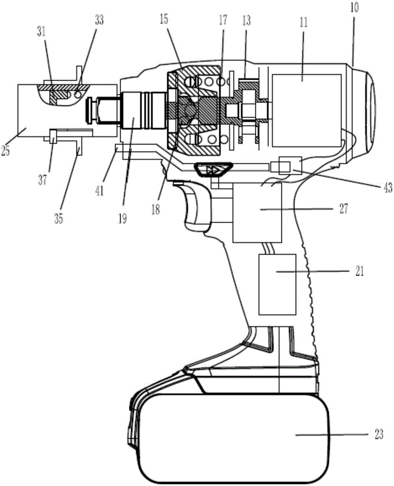
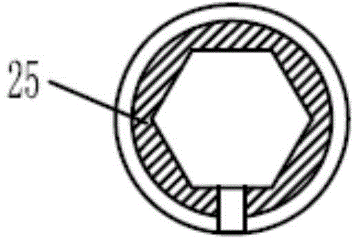
[0031] Such as figure 1 As shown, in the first embodiment of the present invention, the impact wrench includes: a body 10, the body 10 is provided with a motor 11, a main shaft 13 driven by the motor 11, an impact block 15 driven by the main shaft 13, Drive shaft 19 driven by impact block 15 , and sleeve 25 mounted on the distal end of fu...


PUM


Abstract

The invention discloses an impact wrench which comprises a main shaft, an impact block, a driving shaft, a sleeve and an on-off switch; the impact wrench has an impact state and a rotation state, a pressing part which can move in the axial direction of the sleeve is further arranged in the sleeve, and movement of the pressing part to one side of the driving shaft triggers on and off of the on-off switch, so that a motor stops working.Compared with the prior art, the impact wrench can loosen a workpiece on a subject matter and can also intelligently control the workpiece to be unscrewed from the subject matter incompletely, the operation is convenient, the efficiency is high, and the impact wrench better meets the working habit of an operator.

Description


Claims


Application Information

Patent Timeline
Owner SUZHOU BOLAIXI ELECTRICAL APPLIANCE CO LTD
Why Eureka
Try Eureka