AI technical title is built by PatSnap AI team. It summarizes the technical point description of the patent document.
A technology of elevator speed limiter and electromagnet, which is applied in the directions of transportation and packaging, elevators, etc., can solve the problems of insufficient reliability of the sliding car solution, and achieve the effect of preventing the sliding car and improving the reliability.
Active Publication Date: 2018-10-12
LANGFANG JIULIAN MACHINERY CO LTD
View PDF10 Cites 0 Cited by
Summary
Abstract
Description
Claims
Application Information
AI Technical Summary
This helps you quickly interpret patents by identifying the three key elements:
Problems solved by technology
Method used
Benefits of technology
Problems solved by technology
[0007] Therefore, the technical problem to be solved by the present invention is that the reliability of the car rolling solution in the prior art is insufficient
Method used
Image
Click on the blue label to locate the original text in one second.
Reading with bidirectional positioning of images and text.
Examples
Embodiment 1
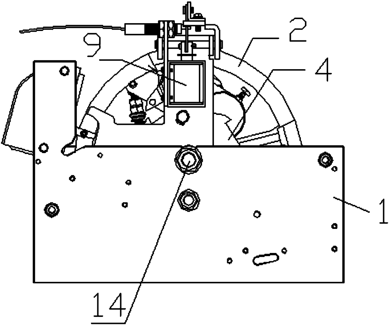
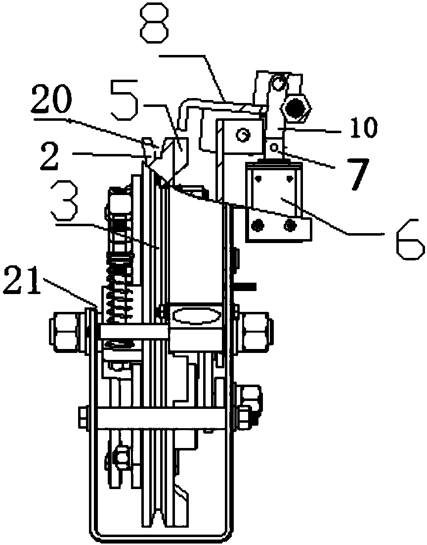
[0037] This embodiment provides an elevator speed governor, which includes a sheave 2, which is rotatably arranged in a box body 1 about a first rotating shaft 14 and has a groove 20, a part of which protrudes out of the opening 21, and the first rotating shaft The two ends of 14 are fixed on the corresponding box wall of the box 1; the wire rope 3 is tensioned and wound in the groove of the sheave 2 to connect the elevator car and drive the car to move synchronously with it; ratchet 4 , Arranged coaxially with the rope wheel 2, a limit device, used to limit the rotation angle of the ratchet wheel 4; a linkage device, arranged between the ratchet wheel 4 and the rope wheel 2, used when the car rolls , Link the ratchet wheel 4 and the rope wheel 2.
[0038] The rope wheel 2 moves synchronously with the car via the wire rope 3, and the ratchet wheel 4 limits the rotation angle of the ratchet wheel 4 by the limiting device. When the car stops at a certain floor, the linkage device ...
Embodiment 2
[0050] This embodiment provides an elevator speed governor, which is a further improvement on the basis of Embodiment 1.
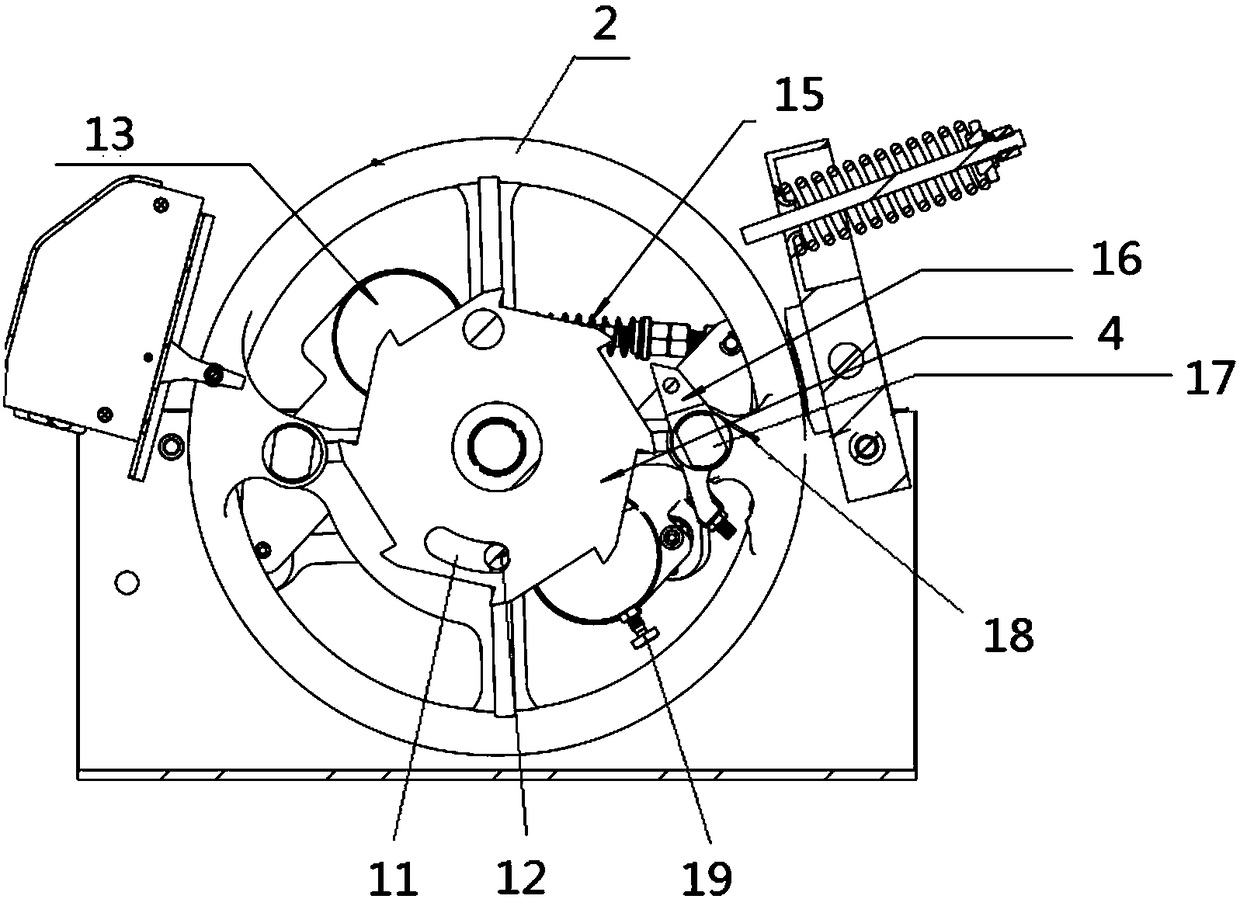
[0051] Such as figure 2 As shown, the elevator speed limiter also includes an overspeed linkage device, and the overspeed linkage device includes
[0052] Two throwing blocks 13 are arranged symmetrically with respect to the first rotation axis, and the two throwing blocks 13 are connected together by a linkage pull rod, and are gathered to the mandrel of the sheave by a coil spring 15;
[0053] The rotating shaft 17 is arranged vertically on the rope wheel;
[0054] The pawl 16 is rotatably arranged on the rotating shaft 17;
[0055] The spring 18 is arranged between the pawl 16 and the rope wheel to provide a force for the pawl 16 to rotate away from the ratchet wheel 4.
[0056] When the rope wheel rotates overspeed, the thrower 13 overcomes the force of the coil spring 15 under the action of centrifugal force, expands outward along the radial direction of the ro...
PUM
Abstract
The invention provides an elevator speed limiter. A rope wheel and a car synchronously move through a steel wire rope; a ratchet wheel limits a self rotating angle through a limiting device. When the car stops at a certain floor, a linkage device is started, so that the ratchet wheel is in linkage with the rope wheel; at the moment, once a car sliding phenomenon occurs, the limiting device firstly limits the rotating range of the ratchet wheel; at the moment, as the ratchet wheel is in linkage with the rope wheel, the rotation of the rope wheel is also limited, and the rope wheel and the car synchronously move through the steel wire rope arranged on the rope wheel in a tensioning manner; after the rotation of the rope wheel is limited, the steel wire rope of the speed limiter lifts and pulls a safety clamp operating handle, a safety clamp brakes the elevator car, and the motion of the car is also limited, so that the effect of controlling car sliding is realized. According to the elevator speed limiter, a phenomenon in the prior art that the car cannot stop due to the simple control of braking of a traction machine (as the secondary braking of the traction machine is not tight) can be effectively avoided.
Description
Technical field [0001] The invention relates to the technical field of elevator speed limiters, in particular to an elevator speed limiter, in particular to a speed limiter that can prevent an elevator from slipping. Background technique [0002] The speed limiter is a component of the elevator overspeed protection device. The speed limiter is installed in the machine room on the top of the elevator, and the tension device is installed in the pit at the bottom of the elevator. The steel wire rope is looped between the speed limiter and the tension device in a closed loop. The tension device makes the wire rope tightly surround the speed limiter. , Make the speed limiter and the elevator car move synchronously at all times. [0003] Elevator overspeed is generally a phenomenon where the elevator's upward or downward speed exceeds 115% of the rated speed. When the elevator is overspeeding, under the action of the centrifugal force generated by the overspeed, the safety switch of th...
Claims
Application Information
Patent Timeline
Application Date:The date an application was filed.
Publication Date:The date a patent or application was officially published.
First Publication Date:The earliest publication date of a patent with the same application number.
Issue Date:Publication date of the patent grant document.
PCT Entry Date:The Entry date of PCT National Phase.
Estimated Expiry Date:The statutory expiry date of a patent right according to the Patent Law, and it is the longest term of protection that the patent right can achieve without the termination of the patent right due to other reasons(Term extension factor has been taken into account ).
Invalid Date:Actual expiry date is based on effective date or publication date of legal transaction data of invalid patent.

