Supercharge Your Innovation With Domain-Expert AI Agents!

A method and apparatus for determining resistance of thermal fluid equipment

A fluid equipment and resistance technology, applied in the field of determining the resistance of thermal fluid equipment, can solve the problems of insufficient calculation accuracy of resistance of complex thermal fluid equipment, and achieve the effect of accurate resistance

Active Publication Date: 2020-08-04
STATE POWER INVESTMENT CORPORATION RESEARCH INSTITUTE CO LTD +1
View PDF3 Cites 0 Cited by
  • Summary
  • Abstract
  • Description
  • Claims
  • Application Information

AI Technical Summary

Problems solved by technology

The purpose of the present invention is to propose a method for determining the resistance of thermal fluid equipment and its equipment to solve the problem of insufficient calculation accuracy of the resistance of complex thermal fluid equipment

Method used


Image

  • A method and apparatus for determining resistance of thermal fluid equipment
  • A method and apparatus for determining resistance of thermal fluid equipment
  • A method and apparatus for determining resistance of thermal fluid equipment

Examples


Embodiment Construction

[0018] Hereinafter, preferred embodiments of the present invention will be described in detail with reference to the accompanying drawings. In the drawings, the same reference numerals are used to designate the same or similar components, although shown in different drawings. For clarity and conciseness, detailed descriptions of known functions and constructions incorporated herein will be omitted so as not to obscure the subject matter of the present invention.

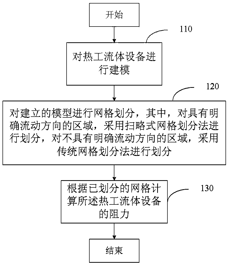
[0019] figure 1 is a simplified flow diagram illustrating the method of the present invention for determining the resistance of a thermal fluid device. The method includes: step 110, modeling the thermal fluid equipment; step 120, performing grid division on the established model, wherein, the area with a clear flow direction is divided by a sweeping grid division method, The traditional grid division method is used to divide the area without a clear flow direction; step 130, calculating the resistance of the therm...


PUM


Abstract

The invention discloses a method and equipment for determining the resistance of thermodynamic fluid equipment. The method comprises the following steps: modeling the thermodynamic fluid equipment; carrying out mesh division on an established model; dividing a region with a definite flowing direction by adopting a sweeping type mesh dividing method, and dividing a region without the definite flowing direction by adopting a traditional mesh dividing method; calculating the resistance of the thermodynamic fluid equipment according to divided meshes. By utilizing the method and the equipment, the accurate calculation of the resistance of the thermodynamic fluid equipment can be realized.

Description

technical field [0001] The invention relates to a thermal fluid system, in particular to a method and equipment for determining the resistance of thermal fluid equipment. Background technique [0002] Most of the current thermal fluid systems are composed of pipes, valves and main equipment. The power of the working fluid flow in the system usually comes from a pump or compressor, and it matches the flow resistance generated by other components. In the design stage, for the selection of power equipment, the resistance of the system must be estimated. [0003] For pipes, valves and other components, due to their relatively simple structure and certain standardization and serialization, empirical formulas are used to calculate their resistance, and the accuracy can meet the requirements. [0004] However, for the main equipment, due to the complex structure and the irregular shape of the flow channel, there is no fixed calculation formula. The method in the prior art is to ...

Claims


Application Information

Patent Timeline
Patent Type & Authority Patents(China)
IPC IPC(8): G06F30/28G06F113/08
Inventor 李京浩姬锋军闫大强王本君陈纲丁炜堃陈义学葛群田林葛炜
Owner STATE POWER INVESTMENT CORPORATION RESEARCH INSTITUTE CO LTD
Features
  • R&D
  • Intellectual Property
  • Life Sciences
  • Materials
  • Tech Scout
  • Unparalleled Data Quality
  • Higher Quality Content
  • 60% Fewer Hallucinations
Learn More