Supercharge Your Innovation With Domain-Expert AI Agents!

Coupling line loading low-pass or band elimination filter with reconfigurable transmission response

A band-stop filter and transmission response technology, applied in the filter field, can solve the problems of single in-band response and uncompact microstrip filter structure, and achieve the effect of simple structure

Active Publication Date: 2020-01-17
NANJING UNIV OF POSTS & TELECOMM
View PDF9 Cites 0 Cited by
  • Summary
  • Abstract
  • Description
  • Claims
  • Application Information

AI Technical Summary

Problems solved by technology

[0004] Purpose of the invention: the purpose of the present invention is to provide a simple structure and easy-to-make novel structure filter for the existing microstrip filter structure which is not compact and has a single response in the band, so that the position of the ripple in the band can be adjusted, And the out-of-band suppression feature is optional

Method used


Image

  • Coupling line loading low-pass or band elimination filter with reconfigurable transmission response
  • Coupling line loading low-pass or band elimination filter with reconfigurable transmission response
  • Coupling line loading low-pass or band elimination filter with reconfigurable transmission response

Examples


Embodiment 1

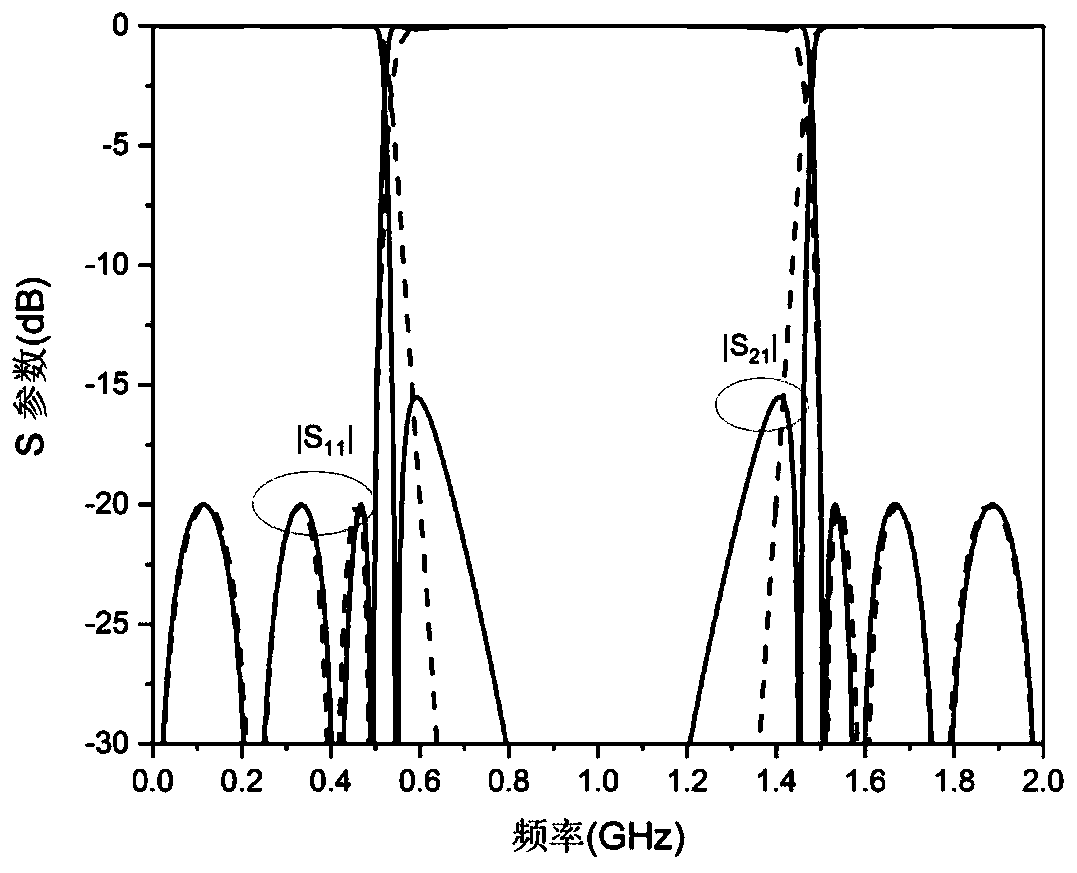
[0023] In this embodiment, the filter bandwidth is 0-500MHz, the S11 is -20dB, and a new type of filter composed of ideal transmission line elements is taken as an example.

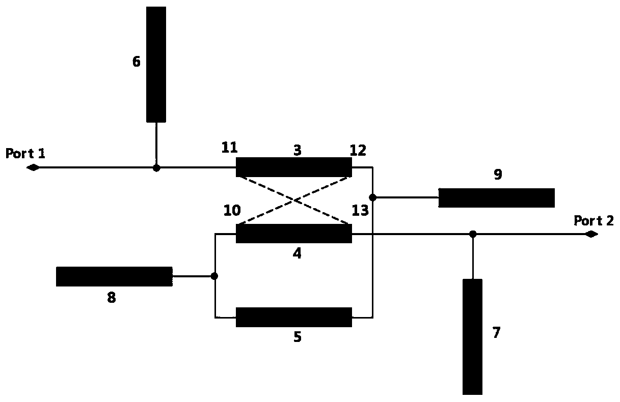
[0024] Such as figure 1 As shown, a coupled line loading low-pass or band-stop filter with reconfigurable transmission response; including: an input port (1), an output port (2), coupled transmission line section one (3) and coupled transmission line section two (4), one uniform transmission line (5), two open stub line one (6) and open stub line two (7) for external loading, two open stub line three (8) and open circuit for internal loading Branch line four (9);

[0025] The coupled transmission line section one (3) includes port one (11) and port two (12), and the coupled transmission line section two (4) includes port three (10) and port four (13);

[0026] On the port three (10) of the coupled transmission line section two (4) and the port two (12) of the coupled transmission line section one (3), t...

Embodiment 2

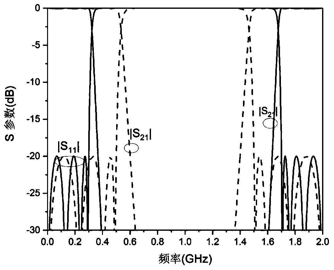
[0039] In this embodiment, the bandwidth of one group of filters is 0-300MHz, and S11 is-20dB; the bandwidth of another group of filters is 0-500MHz, and S11 is-20dB, and a novel filter formed by ideal transmission line components is example.

[0040] Such as figure 1As shown, a coupled line loading low-pass or band-stop filter with reconfigurable transmission response; including: an input port (1), an output port (2), coupled transmission line section one (3) and coupled transmission line section two (4), one uniform transmission line (5), two open stub line one (6) and open stub line two (7) for external loading, two open stub line three (8) and open circuit for internal loading Branch line four (9);

[0041] The coupled transmission line section one (3) includes port one (11) and port two (12), and the coupled transmission line section two (4) includes port three (10) and port four (13);

[0042] On the port three (10) of the coupled transmission line section two (4) and...


PUM


Abstract

The invention discloses a coupling line loading low-pass or band elimination filter with reconfigurable transmission response. The coupling line loading low-pass or band elimination filter comprisesan input port, an output port, a section of coupling transmission line section, a section of uniform transmission line, two sections of externally loaded open-circuit branch lines and two sections ofinternally loaded open-circuit branch lines; according to different filter parameter indexes, a circuit structure meeting requirements can be rapidly synthesized; the structure is simple, and the position of the in-band corrugation is adjustable; the position of the out-of-band transmission zero point is adjustable, that is, the out-of-band rejection has selectivity, and in addition, the attenuation of the transmission response at the integral multiple of the electrical length of 90 degrees is infinite.

Description

technical field [0001] The invention relates to a filter, in particular to a coupled line-loaded low-pass or band-stop filter with reconfigurable transmission response. Background technique [0002] In a communication system, a filter is a very important electronic device. It can effectively filter out some specific frequency points in the communication system or frequency points other than this frequency, so as to ensure that the communication system can transmit signals more efficiently and accurately. [0003] With the rapid development of the communication field, the system has higher and higher requirements for the filter index, which makes the filter smaller and more compact, and has low insertion loss. And it has more selectivity in the band and higher inhibition in the band. Contents of the invention [0004] Purpose of the invention: the purpose of the present invention is to provide a simple structure and easy-to-make novel structure filter for the existing mic...

Claims


Application Information

Patent Timeline
Patent Type & Authority Applications(China)
IPC IPC(8): H01P1/203H01P1/20
CPCH01P1/20H01P1/2039
Inventor 金秀华周玉婷黄晓东
Owner NANJING UNIV OF POSTS & TELECOMM
Features
  • R&D
  • Intellectual Property
  • Life Sciences
  • Materials
  • Tech Scout
  • Unparalleled Data Quality
  • Higher Quality Content
  • 60% Fewer Hallucinations
Learn More