Slim Ironless Brushless Two Pole Permanent Magnet DC Motor

A permanent magnet direct current, slender technology, which is applied in the manufacture of motor generators, electrical components, electromechanical devices, etc., can solve the problems that the motor fails to achieve the maximum efficiency, maximizes the efficiency of the motor, and does not highlight the maximum efficiency of the motor. The effect of small loss, high power density, and maximized motor efficiency

Active Publication Date: 2018-01-30
朱幕松
View PDF8 Cites 0 Cited by
  • Summary
  • Abstract
  • Description
  • Claims
  • Application Information

AI Technical Summary

Problems solved by technology

[0002] At present, iron-core brushless DC motors lead the development direction of DC motors in the future with the advantages of high efficiency, small size, light weight, and no reluctance. There are two types of iron-core brushless DC motors on the market, one It is a disc motor with an axial magnetic circuit, and the other is a coreless motor with a radial magnetic circuit. Although these two motors have their own advantages, their common disadvantage is that neither of them can achieve The ideal goal of maximizing efficiency and minimizing volume and weight, for example, the application number is "201020686151.4", and the name is a utility model patent of "a brushless DC motor with inner and outer rotors without iron core loss", which is a radial magnetic The coreless motor of the road is similar to the principle structure of the existing coreless motor technology of the same type, and neither has the outstanding structural characteristics of maximizing motor efficiency and minimizing volume and weight

Method used


Image

  • Slim Ironless Brushless Two Pole Permanent Magnet DC Motor
  • Slim Ironless Brushless Two Pole Permanent Magnet DC Motor
  • Slim Ironless Brushless Two Pole Permanent Magnet DC Motor

Examples


Embodiment Construction

[0013] The present invention will be further described below in conjunction with the accompanying drawings and embodiments.

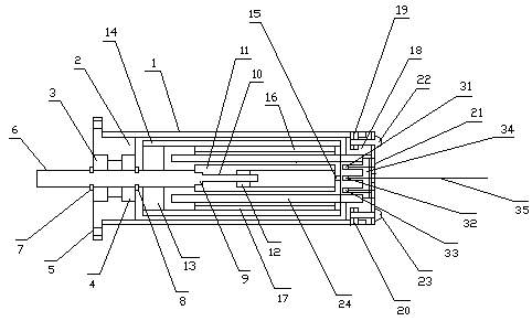
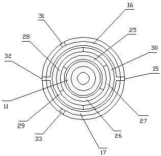
[0014] exist figure 1 , figure 2, middle, the barrel-shaped shell 1 is made of non-magnetic aluminum alloy, the inner circle of the left end of the barrel-shaped shell is tightly fitted with the left end cover 2, the inner circle of the left end cover is provided with a bearing frame, and the inner circles of the left and right ends of the bearing frame are installed with left and right Bearings 3 and 4, the left end of the left end cover is formed with a square flange, and the four corners of the flange are provided with connecting holes 5, and the inner and outer rotors are provided with drive shafts 6, which are installed on the inner circles of the left and right bearings, and are located at the left and right ends of the left bearing. The outer circle of the drive shaft at the right end of the bearing is formed with left and right circlip grooves...


PUM


Abstract

A slender coreless brushless two-pole permanent magnet direct-current motor is composed of a barrel-type shell, an inner rotor, an outer rotor and a coiling armature; a left bearing and a right bearing are arranged at a left end cover of the barrel-type shell, a driving shaft is installed in the left bearing and the right bearing, the inner rotor and the outer rotor are installed at the right end of the driving shaft and are made of a neodymium iron boron strong magnetic material, the inner rotor is a tubular permanent magnet, and an upper permanent magnet and a lower permanent magnet are arranged in a magnetic conductive barrel of the outer rotor; a coil groove is formed in a right end cover of the barrel-type shell, a slender hollow coil is installed in the coil groove, three sensing holes are formed in the right end cover, Hall sensors are installed in the sensing holes, and a three-phase output line and output lines of the three Hall sensors are welded to a printed circuit circular plate of the right end cover and assembled into an output cable. The effective area of cutting magnetic lines in a magnetic field by the slender hollow coil is large, and coil loss is small. The motor has the inherent advantages of being high in efficiency, small in size, light in weight, free of magnetic resistance and the like as a coreless brushless direct-current motor, and the ideal target of the maximum efficiency, minimum size and minimum weight of the motor can be achieved.

Description

technical field [0001] The invention relates to an iron-core-less brushless direct-current motor, to be exact, a slender iron-core-less brushless two-pole permanent-magnet direct-current motor. Background technique [0002] At present, iron-core brushless DC motors lead the development direction of DC motors in the future with the advantages of high efficiency, small size, light weight, and no reluctance. There are two types of iron-core brushless DC motors on the market, one It is a disc motor with an axial magnetic circuit, and the other is a coreless motor with a radial magnetic circuit. Although these two motors have their own advantages, their common disadvantage is that neither of them can achieve The ideal goal of maximizing efficiency and minimizing volume and weight. For example, the application number is "201020686151.4", and the name is a utility model patent of "a brushless DC motor with inner and outer rotors without iron core loss". This is a radial magnetic T...

Claims


Application Information

Patent Timeline
Patent Type & Authority Patents(China)
IPC IPC(8): H02K16/02H02K3/28H02K15/04
CPCH02K3/28H02K15/0492H02K16/02
Inventor 朱幕松
Owner 朱幕松
Why Eureka
Try Eureka