AI technical title is built by Patsnap AI team. It summarizes the technical point description of the patent document.
A bending device, high-efficiency technology, applied in the direction of feeding device, positioning device, storage device, etc., can solve the problems of slow bending speed, complicated operation, poor bending effect, etc., achieve fast bending speed, simple operation, Good bending effect
Active Publication Date: 2017-07-28
山东宏真精工机械有限公司
View PDF7 Cites 2 Cited by
Summary
Abstract
Description
Claims
Application Information
AI Technical Summary
This helps you quickly interpret patents by identifying the three key elements:
Problems solved by technology
Method used
Benefits of technology
Problems solved by technology
[0005] In order to overcome the disadvantages of slow bending speed, poor bending effect and complicated operation of the current steel pipe bending device, the technical problem to be solved by the present invention is to provide a fast bending speed, good bending effect and simple operation. Steel pipe high-efficiency bending device
Method used
Image
Click on the blue label to locate the original text in one second.
Reading with bidirectional positioning of images and text.
Examples
Embodiment 1
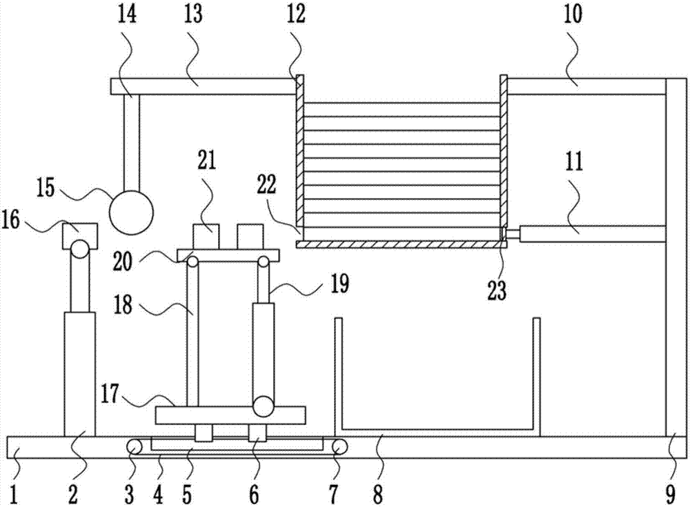
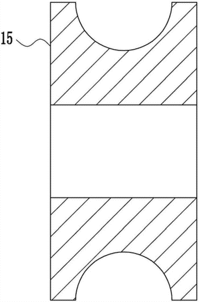
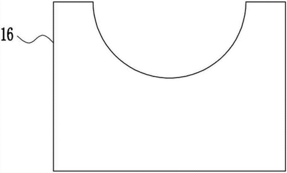
[0024] A steel pipe high-efficiency bending device, such as Figure 1-6 As shown, it includes bottom plate 1, cylinder I2, electric wheel 3, pull wire 4, slide rail 5, slider 6, driven wheel 7, collection box 8, right frame 9, top plate 10, electric push rod I11, material box 12, Support plate 13, bracket 14, pressure roller 15, bracket 16, fixed plate Ⅰ17, cylinder Ⅲ18, cylinder Ⅱ19, fixed plate Ⅱ20, clamping device 21, fixed plate Ⅲ211, baffle 212, electric push rod Ⅱ213, snap ring 214 And the push plate 23, the top left side of the base plate 1 is provided with a cylinder I2, the top of the cylinder I2 is hingedly connected with a bracket 16, and the inside of the base plate 1 is provided with an electric wheel 3, a slide rail 5, a driven wheel 7, and a slide rail 5 in sequence from left to right A slider 6 is arranged symmetrically on the top, and the slider 6 is slidingly connected with the slide rail 5. The electric wheel 3 and the driven wheel 7 are wound with a pull wi...
PUM
Abstract
The invention relates to a bending device, in particular to an efficient steel pipe bending device. According to the technical problems to be solved, the efficient steel pipe bending device provided by the invention is high in bending speed, good in bending effect and easy to operate. By means of the efficient steel pipe bending device provided by the invention, the technical problems can be solved. The efficient steel pipe bending device provided by the invention comprises a bottom plate, a cylinder I, an electric wheel, a pull wire, a sliding rail, sliding blocks, a driven wheel, a collection box, a right frame, a top plate, an electric push rod I, a material box, a support plate, a support, a pressing wheel, a supporting block, a fixed plate I, a cylinder III, a cylinder II, a fixed plate II, a clamping device, a fixed plate III, baffles, electric push rods II, clamping rings and a push plate. The cylinder I is arranged on the left side of the top of the bottom plate. The supporting block is hinged to the top end of the cylinder I. The electric wheel, the sliding rail and the driven wheel are arranged inside the bottom plate sequentially from left to right. The sliding blocks are arranged at the top of the sliding rail symmetrically. Through the efficient steel pipe bending device, the effects of the high bending speed, the good bending effect and easy operation are achieved.
Description
technical field [0001] The invention relates to a bending device, in particular to a high-efficiency bending device for steel pipes. Background technique [0002] The development of steel pipe production technology began with the rise of the bicycle manufacturing industry, the development of petroleum in the early 19th century, the manufacture of ships, boilers, and aircraft during the two world wars, the manufacture of thermal power boilers after the Second World War, the development of the chemical industry and Drilling, production and transportation of oil and natural gas have strongly promoted the development of steel pipe industry in terms of variety, output and quality. The steel pipe is used to transfer fluid and powder, exchange heat and produce mechanical parts and containers, what's more it's a kind of economical steel. Using steel pipes to manufacture building structure grids, pillars and mechanical supports can reduce weight, save metal by 20-40%, and realize fa...
Claims
Application Information
Patent Timeline
Application Date:The date an application was filed.
Publication Date:The date a patent or application was officially published.
First Publication Date:The earliest publication date of a patent with the same application number.
Issue Date:Publication date of the patent grant document.
PCT Entry Date:The Entry date of PCT National Phase.
Estimated Expiry Date:The statutory expiry date of a patent right according to the Patent Law, and it is the longest term of protection that the patent right can achieve without the termination of the patent right due to other reasons(Term extension factor has been taken into account ).
Invalid Date:Actual expiry date is based on effective date or publication date of legal transaction data of invalid patent.

