Steel bar bending device for building construction

A technology for steel bar bending and building construction, applied in engineering safety devices, manufacturing tools, metal processing and other directions, it can solve problems such as the position that affects the bending of steel bars, the poor fixing effect of steel bars, and easy changes, so as to achieve stable and stable bending process. The effect of convenient processing and fast bending speed

Inactive Publication Date: 2021-04-09
云南建丰实业(集团)有限公司
View PDF0 Cites 0 Cited by
  • Summary
  • Abstract
  • Description
  • Claims
  • Application Information

AI Technical Summary

Problems solved by technology

Including smooth round steel bars, ribbed steel bars, and twisted steel bars. Due to the different requirements for steel bars on construction sites, construction workers will use steel bar bending devices to bend steel bars for use. The existing building construction steel bar bending devices are easy to operate , but the fixing effect on the steel bar is poor when the steel bar is bent, and the steel bar is easy to pop out of the bending groove after being stressed, which is very dangerous. At the same time, the position of the steel bar in the bending device is easy to change when it is bent, which directly affects the bending position of the steel bar , so we propose a steel bar bending device for building construction

Method used


Image

  • Steel bar bending device for building construction
  • Steel bar bending device for building construction
  • Steel bar bending device for building construction

Examples


Embodiment 1

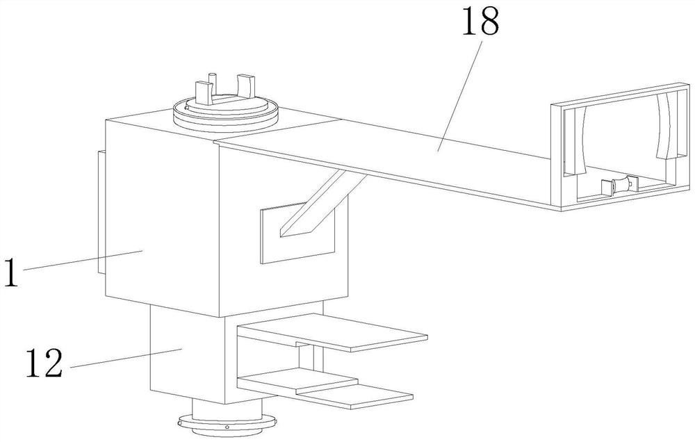
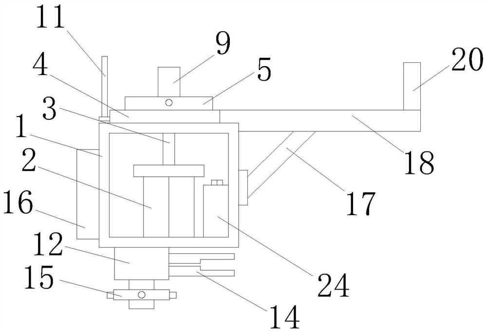
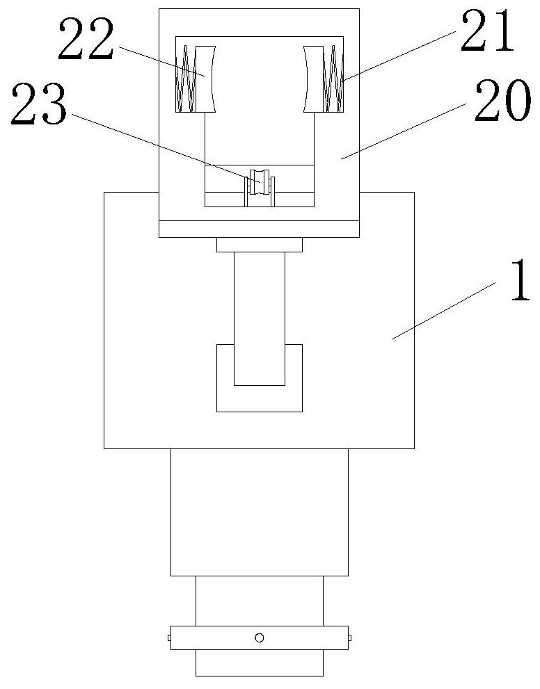
[0027] Embodiment 1, according to Figure 1-Figure 6 , by rotating the steering block 15, the second threaded rod 13 is driven to rotate through the steering block 15, and the two second splints 14 are brought close to each other through the screw thread, clamping the edge of the workbench, and fixing the bending device on the workbench. The overall device can be conveniently installed on the workbench for easy processing. After placing the steel bar that needs to be bent on the roller 23 provided inside the limit frame 20, the third splint 22 is under the action of the spring 21 at this time. Clamp and fix one end of the steel bar, and then continue to deliver the steel bar forward until it is sent between the two first splints 9, at this time, by rotating the first threaded rod 8, the two first splints 9 clamp the steel bar to fix the steel bar The end of the steel bar can be marked with the help of the measuring ruler 19, and the two ends of the steel bar can be well fixed....

Embodiment 2

[0028] Embodiment 2, according to Figure 1-Figure 6, when bending, the control panel 16 controls the action of the motor 2, the rotation of the output end of the motor 2, and the smooth rotation of the motor 2 to realize the bending, which not only reduces the work intensity of the workers, but also reduces the pressure of the smooth bending. The pop-up of the steel bars due to uneven stress protects the lives of workers. When the bearing plate 7 rotates, when the steel bars are in contact with the positioning columns 11, the position of the positioning columns 11 is fixed. Through the cooperation of the positioning columns 11, the steel bars Bending is carried out so that the position of each bending point remains unchanged, which will not affect the bending position of the steel bar and ensure the quality of the bending.

[0029] Working principle: when in use, install the bending device on the workbench, rotate the steering block 15, drive the second threaded rod 13 to rot...


PUM


Abstract

The invention discloses a steel bar bending device for building construction. The steel bar bending device comprises a mounting box, a motor is installed in the middle of the bottom end of the interior of the mounting box, a storage battery is installed at one end of the bottom of an inner cavity of the mounting box, a connecting rod is installed at the output end of the motor, a fixed disc is installed at the top of the mounting box, a circular ring is installed at the top of the fixed disc, a steel ball is arranged in the circular ring, a bearing plate is installed at the top of the connecting rod, a first threaded rod is rotatably installed in the bearing plate, a first clamping plate is installed on the outer surface of the first threaded rod in a threaded mode, and a fixing rod is installed on the outer surface of the circular ring. The steel bar bending device is simple in structure and convenient to install, bending operation is carried out under the action of the output end of the motor, compared with manual bending, the bending process is more stable, the bending speed is higher, the situation that due to unstable manual force application, a steel bar is stressed and popped up is avoided, and the life safety of a user is protected.

Description

technical field [0001] The invention relates to the technical field of building construction, in particular to a steel bar bending device for building construction. Background technique [0002] Reinforcement refers to steel for reinforced concrete and prestressed reinforced concrete, which is circular in cross-section and sometimes square with rounded corners. Including smooth round steel bars, ribbed steel bars, and twisted steel bars. Because construction sites have different requirements for steel bars, construction workers will use steel bar bending devices to bend steel bars for use. The existing building construction steel bar bending devices are easy to operate , but the fixing effect on the steel bar is poor when the steel bar is bent, and the steel bar is easy to pop out of the bending groove after being stressed, which is very dangerous. , so we propose a steel bar bending device for building construction. Contents of the invention [0003] The object of the p...

Claims


Application Information

Patent Timeline
Patent Type & Authority Applications(China)
IPC IPC(8): B21F1/00B21F23/00B21C51/00F16P1/00
CPCB21C51/00B21F1/00B21F23/00F16P1/00
Inventor 不公告发明人
Owner 云南建丰实业(集团)有限公司
Why Eureka
Try Eureka