Double ejection mechanism and injection mold

A secondary ejection and secondary ejection technology, which is applied in the field of molds, can solve the problems of complex mold structure, low quality, and low reliability, and achieve the effects of avoiding stuck failure, improving service life, and strong stability

Active Publication Date: 2016-07-20
SHENZHEN SILVER BASIS TECH
View PDF1 Cites 0 Cited by
  • Summary
  • Abstract
  • Description
  • Claims
  • Application Information

AI Technical Summary

Problems solved by technology

[0002] The traditional secondary ejection type control structure, non-mechanical types include: magnetic switch and nylon switch, which have the problems of small fastening force, insufficient structural strength, easy fracture and low reliability under heavy load clamping, It can only be applied to small and medium-sized molds; in addition, some mechanisms use springs and other drive devices that are prone to failure, and there are also problems such as insufficient structural strength and low reliability; at the same time, there are also problems such as some structures occupy a large space and are complicated to install.
Part of the structure that uses the oil cylinder structure to control the secondary parting and ejection has a large fastening force, but there are problems such as complex mold structure and expensive oil cylinder, and it also needs supporting facilities such as oil nozzle / oil pipe / induction circuit / oil pump to increase the mold and Injection molding costs, while producing oil pollution, causing problems such as uncleanliness

Method used


Image

  • Double ejection mechanism and injection mold
  • Double ejection mechanism and injection mold
  • Double ejection mechanism and injection mold

Examples


Embodiment 1

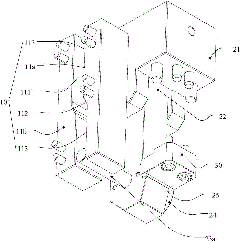
[0030] Embodiment 1 of the present invention: the guide 10 includes two stoppers (11a, 11b) provided with a gap, the gap forms a guide groove 111, the guide groove 111 has an inclined section 112 and a straight section 113, and the first drag hook 22 is away from its hinge. There is a swing arm 23a extending into the guide groove 111 at the axial position. The working process of split type ejection control is as follows: during one ejection process, the swing arm 23a moves along the straight line section 113, the first drag hook 22 is hooked on the second ejector plate 500, and the second ejector plate 500 follows the first ejector plate 400 Move, when the first pull hook 22 moves to the secondary ejection station with the first ejector plate 400 and the second ejector plate 500, the inclined section 112 forces the first pull hook 22 to swing, and releases the second ejector plate 500, the second ejector plate 500 The ejector plate 500 stops moving, and the first ejector plate...

Embodiment 2

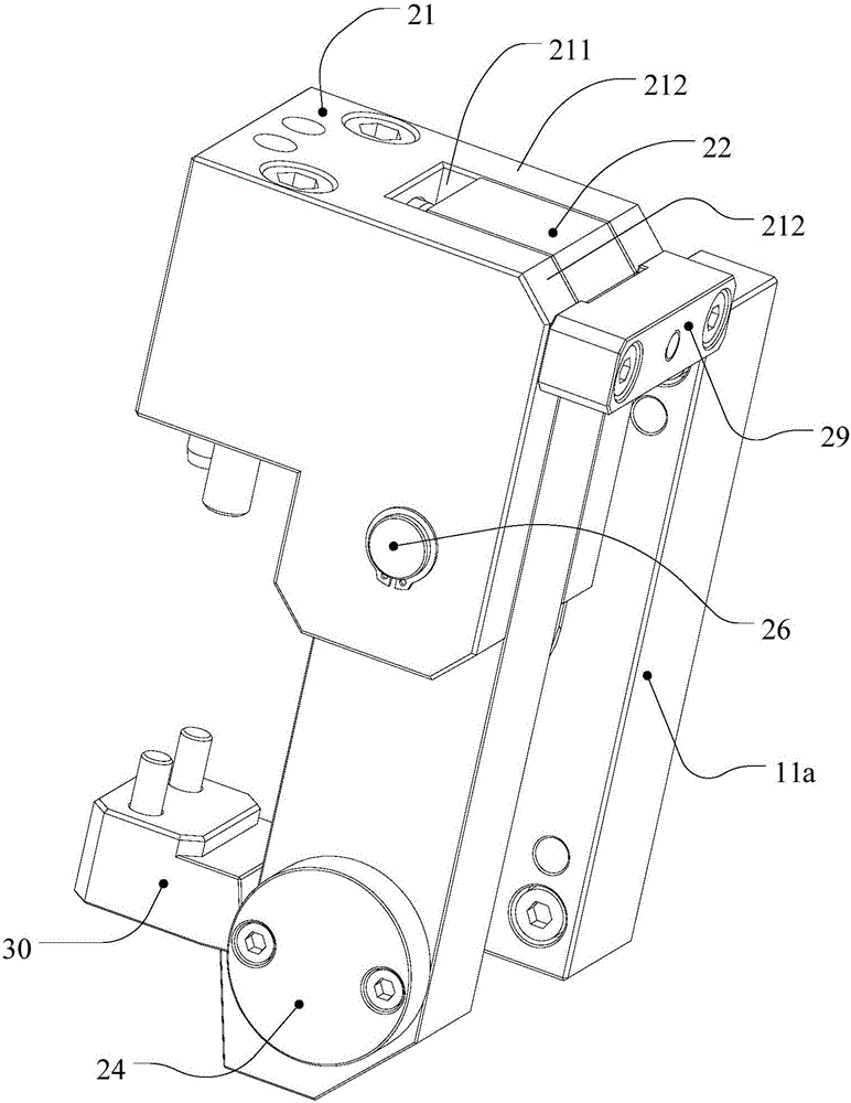
[0031] Embodiment 2 of the present invention: refer to figure 2, the guide 10 is a cam structure, the cam surface of the cam structure has an inclined section (112') and a straight section (113'), the first pull hook 22 has a swing arm 23b extending to contact with the cam surface, and a spring is arranged in the bracket 21 Reset piece (not marked). The working process of splitting ejection control is as follows: in the process of one ejection, the swing arm 23b moves along the straight line (113'), the first pull hook 22 is hooked on the second ejector plate 500, and the second ejector plate 500 follows the first ejector plate. The ejector plate 400 moves, and when the first pull hook 22 moves to the secondary ejection station along with the first ejector plate 400 and the second ejector plate 500, the inclined section (112') drives the swing arm 23a to force the first pull hook 22 to swing, and The second ejector plate 500 is released, the second ejector plate 500 stops mo...


PUM


Abstract

The invention discloses a double ejection mechanism and an injection mold, wherein the double ejection mechanism comprises a guide piece detachably connected to a die support, a bracket detachably connected to a first ejector plate of the die, and a first drag hook hinged to the bracket; the first drag hook is matched with the guide piece; during primary ejection, the first drag hook is hooked on a second ejector plate of the die, and the second ejector plate moves along with the first ejector plate; and when the first drag hook moves to a secondary ejection station along with the first ejector plate and the second ejector plate, the guide piece drives the first drag hook to swing, the second ejector plate is released and stops moving, and the first ejector plate continues to move and complete secondary ejection. The technical scheme is simple in structure, strong in practicability, high in reliability, convenient to operate, steady in structure and easy to machine.

Description

technical field [0001] The invention relates to the technical field of molds, in particular to a secondary ejection mechanism and an injection mold. Background technique [0002] The traditional secondary ejection type control structure, non-mechanical types include: magnetic switch and nylon switch, which have the problems of small fastening force, insufficient structural strength, easy fracture and low reliability under heavy load clamping, It can only be applied to small and medium-sized molds; in addition, some mechanisms use springs and other drive devices that are prone to failure, and there are also problems such as insufficient structural strength and low reliability; at the same time, there are also problems such as some structures occupy a large space and are complicated to install. Part of the structure that uses the oil cylinder structure to control the secondary parting and ejection has a large fastening force, but there are problems such as complex mold structu...

Claims


Application Information

Patent Timeline
Patent Type & Authority Applications(China)
IPC IPC(8): B29C45/40B29C45/26
CPCB29C45/2606B29C45/4005
Inventor 黄清刚胡作寰熊向军彭时坤吴尚
Owner SHENZHEN SILVER BASIS TECH
Why Eureka
Try Eureka