Multi-liquid transmission rotary device and pipe grabber

A slewing device, multi-fluid circuit technology, applied in the direction of pipe components, pipe laying and maintenance, pipes/pipe joints/pipe fittings, etc., can solve the problem that hydraulic oil pipes cannot achieve dynamic and static state transformation.

Active Publication Date: 2018-05-01
BC P INC CHINA NAT PETROLEUM CORP +2
View PDF6 Cites 0 Cited by
  • Summary
  • Abstract
  • Description
  • Claims
  • Application Information

AI Technical Summary

Problems solved by technology

[0004] The embodiment of the present application provides a multi-fluid transmission rotary device and a pipe grabber, which can effectively solve the technical problem that the hydraulic oil pipes of the multi-fluid transmission rotary device in the prior art cannot achieve dynamic and static state conversion, and realize the multi-fluid circuit. The hydraulic oil circuit of the transmission and slewing device can meet the technical effect of dynamic and static state conversion

Method used


Image

  • Multi-liquid transmission rotary device and pipe grabber
  • Multi-liquid transmission rotary device and pipe grabber
  • Multi-liquid transmission rotary device and pipe grabber

Examples


Embodiment 1

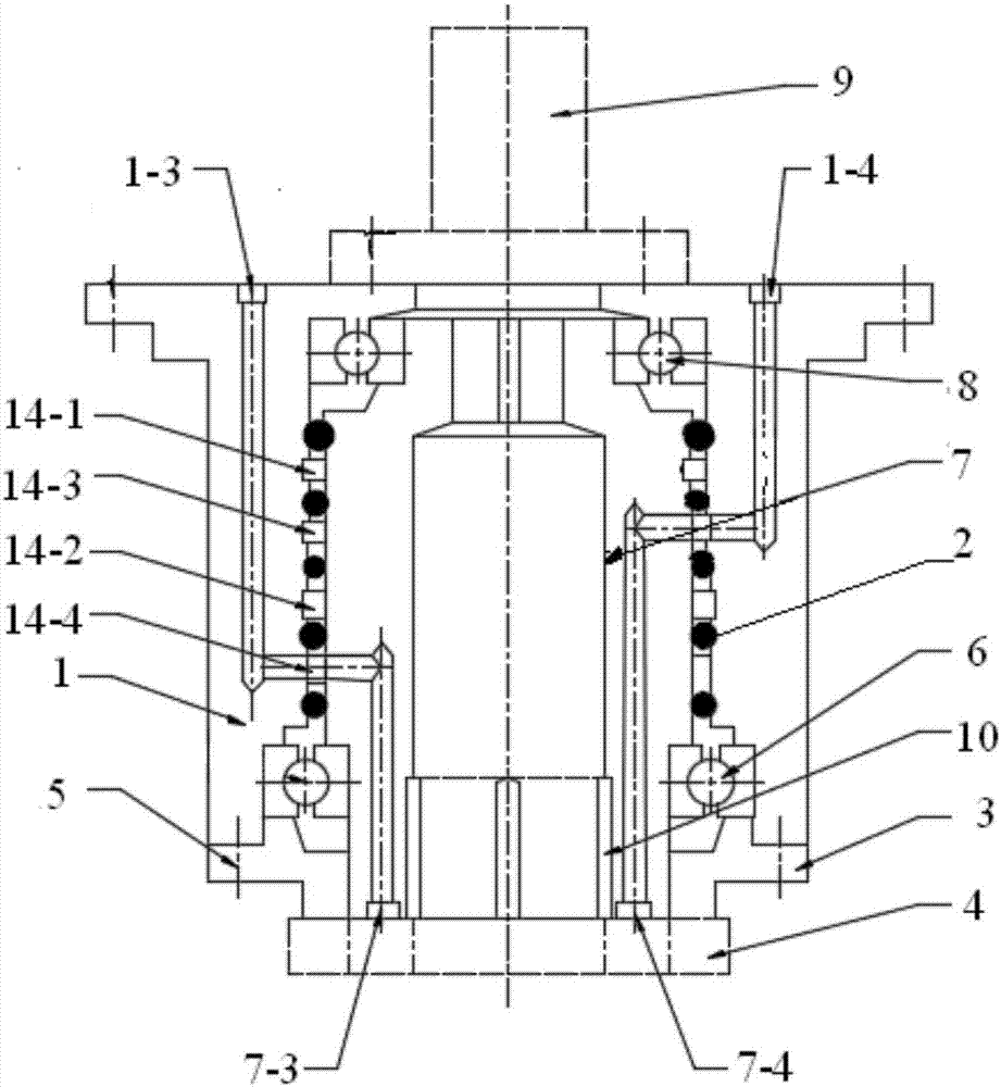
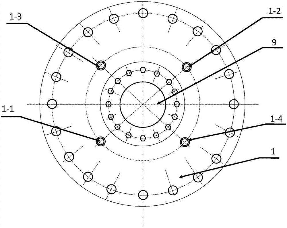
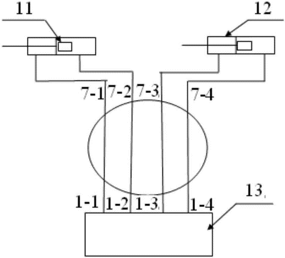
[0038] like figure 1 , figure 2 , image 3 As shown, the embodiment of the present invention provides a multi-fluid transmission rotary device, which is applied to a special pipe grabber, wherein the pipe grabber includes a side thrust hydraulic cylinder group 11, a pipe grab hydraulic cylinder group 12 and a control system valve group 13. The multi-fluid transmission rotary device includes: a fixed sleeve 1, a rotary mechanism and a driving cylinder 9.

[0039] The fixed sleeve 1 is provided with a first oil pipe 1-1, a second oil pipe 1-2, a third oil pipe 1-3 and a fourth oil pipe 1-4, the first oil pipe 1-1, the second oil pipe 1-2, the third oil pipe The oil pipe 1-3 and the fourth oil pipe 1-4 are respectively connected with the valve group 13 of the control system.

[0040] The slewing mechanism is arranged at the center of the fixed sleeve 1, and the slewing mechanism is provided with a fifth oil pipe 7-1, a sixth oil pipe 7-2, a seventh oil pipe 7-3 and an eighth ...

Embodiment 2

[0054] like figure 1 , figure 2 As shown, a multi-fluid transmission rotary device provided in the embodiment of the present application drives the rotary drive cylinder 9 to rotate when performing rotary work, so that the rotary shaft 7 is rotated relative to the fixed sleeve 1 under the action of the driving force of the rotary drive cylinder 9 sports. The first bearing 6 and the second bearing 8 are fixed in the inner circular step of the fixed sleeve 1, and at the same time, the rotating shaft 7 is fixed between the first bearing 6 and the second bearing 8, so that the rotating shaft 7 rotates smoothly and the rotation resistance is small .

[0055] combine image 3 As shown, the multi-fluid transmission rotary device provided by the embodiment of the present application is between the fixed sleeve 1 and the rotating shaft 7, providing a 2-in-2 hydraulic cylinder group 11 and a pipe-grabbing hydraulic cylinder group 12 in the outer rotary structure. Out of the hydraul...

Embodiment 3

[0057] The embodiment of the present application also provides a pipe grabber, the pipe grabber includes the above-mentioned multi-liquid path transmission rotary device.


PUM


Abstract

The invention discloses a multi-liquid channel transferring and rotating device. The multi-liquid channel transferring and rotating device comprises a fixing sleeve, a rotating mechanism and a drive cylinder; the fixing sleeve is provided with a first oil pipe, a second oil pipe, a third oil pipe and a fourth oil pipe; the rotating mechanism is provided with a fifth oil pipe, a sixth oil pipe, a seventh oil pipe and an eighth oil pipe, wherein the fifth oil pipe communicates with the first oil pipe, the sixth oil pipe communicates with the second oil pipe, the seventh oil pipe communicates with the third oil pipe, and the eighth oil pipe communicates with the fourth oil pipe; the drive cylinder drives the rotating mechanism to rotate in the fixing sleeve. The invention further discloses a vehicle pipe grabbing device. According to the multi-liquid channel transferring and rotating device and the pipe grabbing device, the technical effect of conversion between the dynamic state and the static state of a hydraulic oil channel of the multi-liquid channel transferring and rotating device can be realized.

Description

technical field [0001] The invention relates to the technical field of hydraulic oil circuit transmission, in particular to a multi-hydraulic circuit transmission rotary device and a pipe grabber. Background technique [0002] In the construction of long-distance pipelines, in water networks and mountainous steep slopes, due to terrain or ground endurance, excavators are generally used to assist in lifting and unloading steel pipes, and slings are usually used to unload pipes. When unloading pipes with slings, manual cooperation is required, which is unsafe; therefore, researchers installed a hydraulic pipe grabber at the end of the excavator, which can use the hydraulic power of the excavator as the driving force to load and unload the pipe. The hydraulic pipe grabber can The grasped steel pipes are rotated and sideways to adapt to the site terrain. In order to realize the rotation and side swing of the hydraulic pipe grabber, the hydraulic pipe grabber is equipped with a ...

Claims


Application Information

Patent Timeline
Patent Type & Authority Patents(China)
IPC IPC(8): F16L39/06F16L1/06
CPCF16L1/06F16L39/06
Inventor 王立虹丁英利吴大伟吴寅虎刘洁
Owner BC P INC CHINA NAT PETROLEUM CORP
Why Eureka
Try Eureka