LED lamp mechanism capable of moving annularly

A kind of LED lamp, mobile technology, applied in the parts of lighting devices, semiconductor devices of light-emitting elements, lighting and heating equipment, etc., can solve the problem that the irradiation range and irradiation angle cannot be adjusted, and cannot meet the different needs of users, etc.

Inactive Publication Date: 2016-07-20
YANGZHOU BAODIAN LANDSCAPE LIGHTING CO LTD
View PDF4 Cites 8 Cited by
  • Summary
  • Abstract
  • Description
  • Claims
  • Application Information

AI Technical Summary

Problems solved by technology

[0002] Existing LED lamps are generally directly fixed at one position, and the irradiation range and irradiation angle cannot be adjusted, which cannot meet the different needs of users, so it is necessary to improve

Method used


Image

  • LED lamp mechanism capable of moving annularly
  • LED lamp mechanism capable of moving annularly
  • LED lamp mechanism capable of moving annularly

Examples


Embodiment Construction

[0026] The specific implementation manners of the present invention will be further described in detail below in conjunction with the accompanying drawings and embodiments. The following examples are used to illustrate the present invention, but are not intended to limit the scope of the present invention.

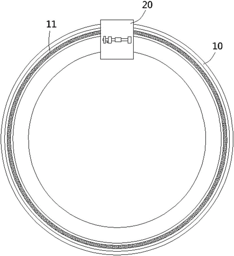
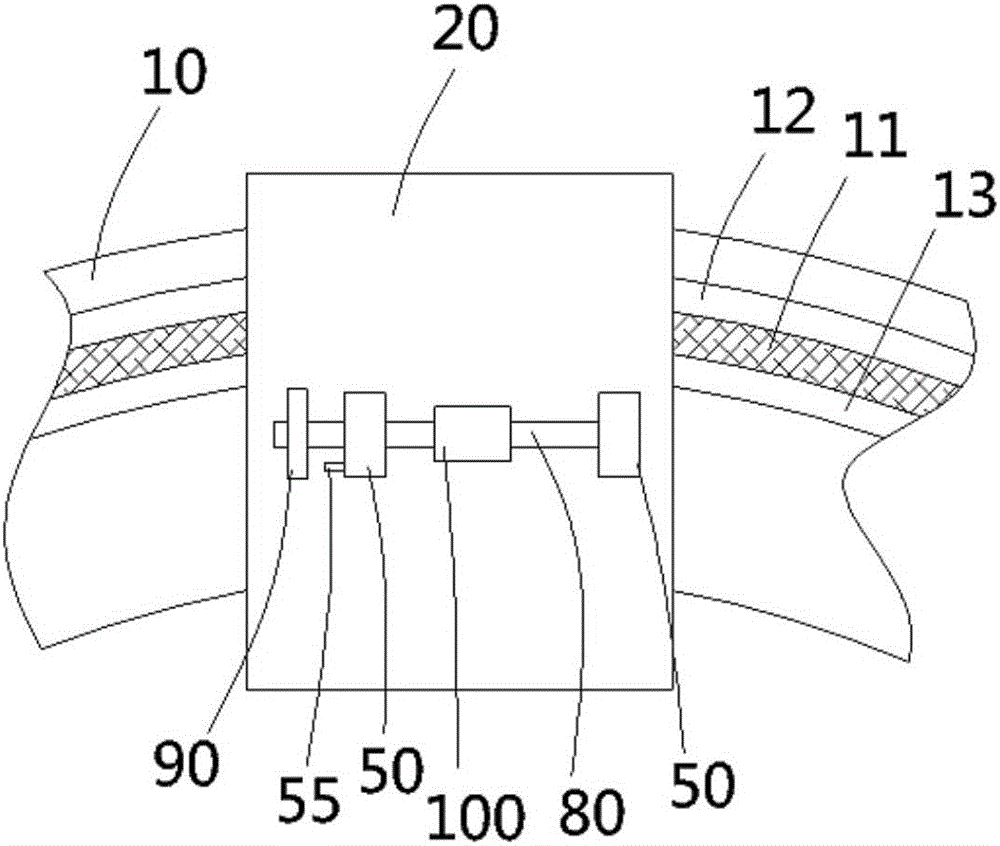
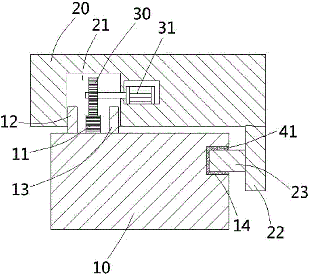
[0027] see Figure 1 to Figure 3 , a circular mobile LED light mechanism according to the present invention, comprising a circular track 10, a lamp holder 20 is arranged on the circular track, and an annular rack portion 11 is provided on the top surface of the circular track 10, and the lamp holder The bottom surface of 20 is formed with an arc-shaped insertion groove 21, and the ring track 10 on the front and rear sides of the rack portion 11 is formed with a first protective plate 12 and a second protective plate 13, and the first protective plate 12 and The second protective plate 13 is ring-shaped and higher than the rack portion 11, the first protective plate 12 and...


PUM


Abstract

The invention discloses an LED lamp mechanism capable of moving annularly. The LED lamp mechanism capable of moving annularly comprises an annular track, wherein a lamp seat is arranged on the annular track; an annular rack is arranged on the top surface of the annular track; an arc-shaped inserting groove is formed in the bottom surface of the lamp seat; the rack part is inserted in the inserting groove; a transmission gear is hinged to the inside of the inserting groove and is engaged with the rack part; a pair of vertical moving grooves is formed in the top surface of the lamp seat; a pair of vertical plates is inserted in the moving grooves; a moving rack is formed on a side wall of the lower part of each vertical plate; each moving rack is connected with a rotating gear in an engaged manner; a locking mechanism is arranged on one side of each rotating gear and in the lamp seat; the upper ends of the vertical plates are hinged to an outer spline shaft; one end of the outer spline shaft extends out of one of the vertical plates and an adjusting plate fixedly sleeves the end of the outer spline shaft; a lamp shell sleeves the outer spline shaft; and an LED lamp is arranged in the lamp shell. The illumination range and the illumination angle of the LED lamp can be adjusted, so that different using demands are met.

Description

Technical field: [0001] The invention relates to the technical field of LED lamp manufacturing, in particular to a ring-moving LED lamp mechanism. Background technique: [0002] Existing LED lamps are generally directly fixed at one position, and the irradiation range and irradiation angle cannot be adjusted, so they cannot meet the different needs of users, so it is necessary to improve them. Invention content: [0003] The object of the present invention is to solve the problems existing in the prior art, and to provide a circular movable LED lamp mechanism that can adjust the irradiation range and irradiation angle of the LED lamp to meet different usage needs. [0004] The invention relates to a circular movable LED lamp mechanism, comprising a circular track, a lamp holder is arranged on the circular track, an annular rack portion is formed on the top surface of the circular track, and an arc shape is formed on the bottom surface of the lamp holder. The rack portion ...

Claims


Application Information

Patent Timeline
Patent Type & Authority Applications(China)
IPC IPC(8): F21S8/00F21V14/02F21V21/14F21V21/34F21Y115/10
CPCF21S8/00F21V14/02F21V21/14F21V21/34
Inventor 付淑珍
Owner YANGZHOU BAODIAN LANDSCAPE LIGHTING CO LTD
Why Eureka
Try Eureka