An automobile instrument pointer shaft detection device

A detection device and automotive instrument technology, applied in the direction of angle/taper measurement, etc., can solve the problems of large error, fuzzy detection results, single detection type, etc., and achieve the effect of eliminating manual operation errors, rapid detection, and accurate detection results.

Active Publication Date: 2018-10-02
AEROSPACE HI TECH HLDG GROUP
View PDF5 Cites 0 Cited by
  • Summary
  • Abstract
  • Description
  • Claims
  • Application Information

AI Technical Summary

Problems solved by technology

[0003] The present invention is to solve the problem that the traditional detection pointer shaft is manually placed on the small optical axis, the non-critical parts are detected by the feeler gauge, and the size of the key part of the pointer shaft is obtained by means of theoretical calculations. There are problems of fuzzy detection results, large errors and single detection types , and further provide an automobile meter pointer shaft detection device

Method used


Image

  • An automobile instrument pointer shaft detection device
  • An automobile instrument pointer shaft detection device
  • An automobile instrument pointer shaft detection device

Examples


specific Embodiment approach 1

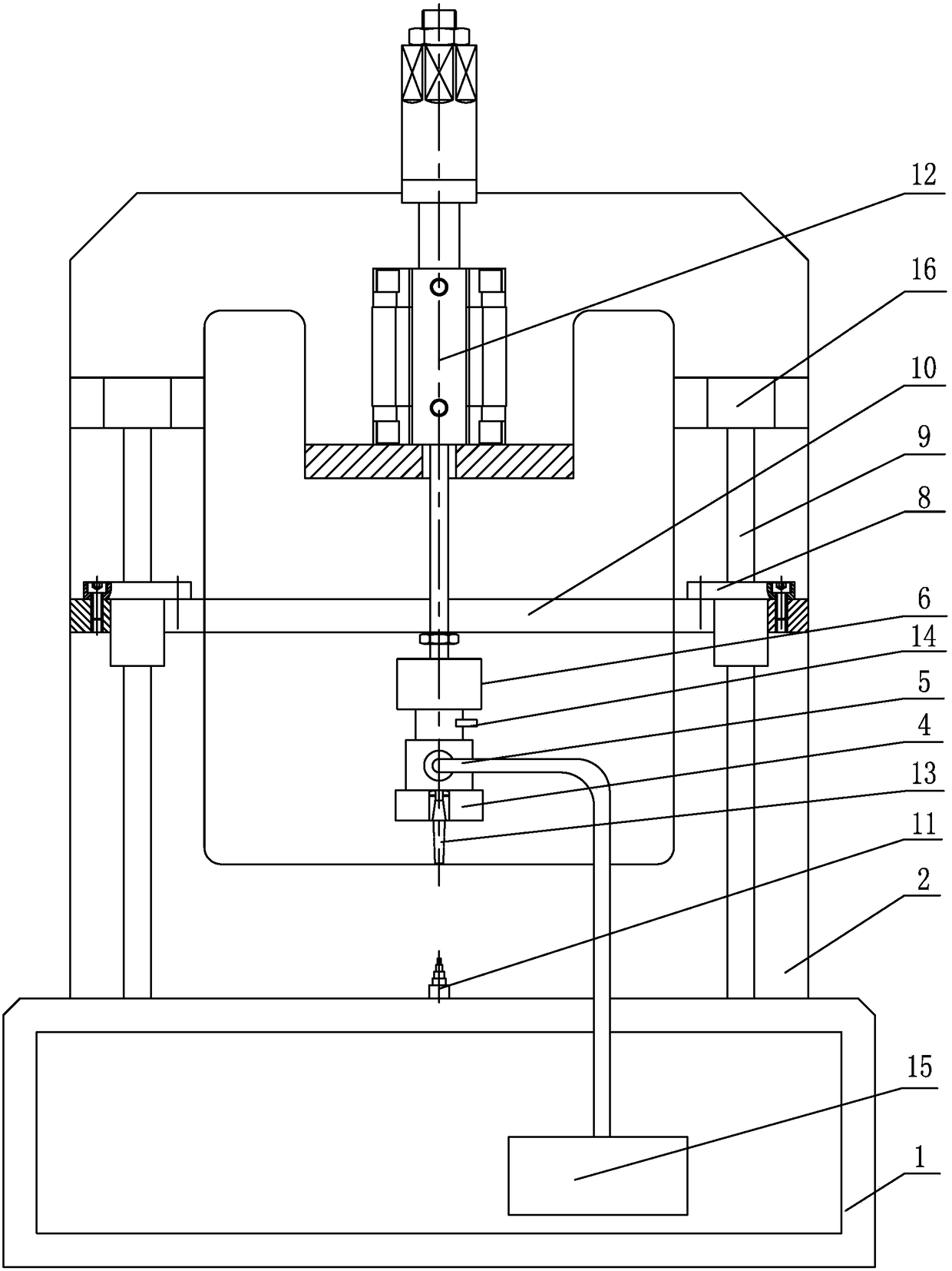
[0011] Specific implementation mode one: combine Figure 1-Figure 3 Explain, a kind of automobile meter pointer axis detection device of this embodiment, it comprises base 1, vertical board 2, pointer holder 4, linear bearing 8, pointer plate 10, cylinder 12, vacuum pump 15 and two guide posts 9;

[0012] The base 1 is fixed with a vertical plate 2, and two guide columns 9 are arranged side by side and installed vertically on the base 1; each of the two guide columns 9 is equipped with a linear bearing 8, and the pointer plate 10 is arranged horizontally and installed on two On the linear bearing 8, the pointer shaft 11 is installed on the base 1, and the vertically arranged cylinder 12 is installed on the vertical plate 2 above the pointer plate 10; the driving rod of the cylinder 12 passes through the pointer plate 10 and the two are fixedly connected, and the cylinder The end of the driving rod 12 is connected with the pointer holder 4, the pointer holder 4 is provided with...

specific Embodiment approach 2

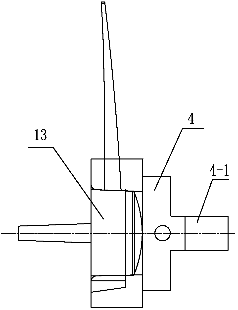
[0014] Specific implementation mode two: combination figure 1 Note that the instrument pointer shaft detection device of this embodiment also includes a tension-pressure sensor 6, one end of the tension-pressure sensor 6 is connected to the end of the driving rod of the cylinder 12, and the other end of the tension-pressure sensor 6 is inserted into the pointer holder 4 The casing 4-1 and the two are fixed by the top wire 14. Such setting facilitates the circumferential movement of the pointer holder 4 and meets the needs of multi-angle detection of the pointer shaft. Others are the same as in the first embodiment.

specific Embodiment approach 3

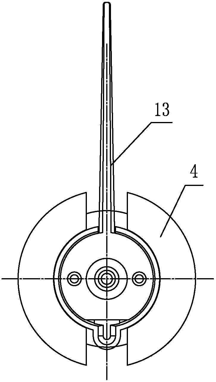
[0015] Specific implementation mode three: combination Figure 4 Explain that the pointer shaft 11 of this embodiment is a five-step shaft, and the pointer shaft 11 is mainly made of a detection part 11-1 and a fixed connection part 11-2. The detection part 11-1 is a five-step shaft section, and the fixed connection part 11 -2 is a fixed segment, when the pointer shaft 11 is vertically inverted, the first-stage shaft segment of the detection part 11-1 is arranged facing the pointer 13, and the fixed connection part 11-2 is connected with the base 1. like image 3 As shown, the pointer shaft 11 of this embodiment can be a five-step shaft, and the pointer shaft 11 is mainly made of a detection part 11-1 and a fixed connection part 11-2. The detection part 11-1 is a five-step shaft section, fixedly connected The part 11 - 2 is a fixed section. When the pointer shaft 11 is inverted, the central axis of the detection part 11 - 1 is arranged facing the pointer 13 . The fixed connec...


PUM


Abstract

The invention discloses a detector for a pointer shaft of an automobile instrument, relates to shaft detectors and aims at solving the problems that in traditional detection a pointer shaft is placed in a small optical axis manually, a non-key part is detected by a filler gauge, the size of a key part of the pointer shaft is obtained via theoretical reckoning, and further a detection result is fuzzy and inaccurate and has large error and the detection type is single. The detector comprises a pedestal, a vertical plate, a pointer fixing seat, a linear bearing, a pointer plate, a cylinder, a vacuum pump and two guide posts, the vertical plate is fixedly mounted on the pedestal, the two guide posts are arranged on the pedestal in parallel vertically, the vertical plate over the pointer plate is provided with the cylinder which is arranged vertically, a driving rod of the cylinder penetrates the pointer plate and is fixedly connected with the pointer plate, the tail end of the driving rod of the cylinder is connected with the pointer fixing seat, the pointer fixing seat is provided with a vacuum cavity communicated with an installation groove, and the vacuum pump is communicated with the vacuum cavity of the pointer fixing seat via a negative-pressure air tube. The detector is used for instrument pointer shaft detection.

Description

technical field [0001] The invention relates to a shaft detection device, in particular to a pointer shaft detection device of an automobile meter. Background technique [0002] When the pointer shaft is detected in the traditional way, the pointer shaft is inserted into the small optical axis in the detection hole, so that the pointer stands upright on the detection end surface, and after the detection end surface rises to a certain position, the gap between the end surface and the pointer cap end surface is detected by a feeler gauge. Because the pointer is manually placed on the small optical axis, the direction and strength of the placement are unstable, and the results obtained are not accurate. Moreover, there is no reference object for comparison, and the inspectors cannot detect intuitively. They can only use a feeler gauge to detect non-critical parts, so as to perform theoretical calculations. The results are vague, unclear, and have large errors. There is a singl...

Claims


Application Information

Patent Timeline
Patent Type & Authority Patents(China)
IPC IPC(8): G01B5/25
CPCG01B5/25
Inventor 张志波石磊冯钢杨朦肖芳慧冯国新张昆刘明月杜维平
Owner AEROSPACE HI TECH HLDG GROUP
Why Eureka
Try Eureka