A heat treatment experimental device

The technology of an experimental device and a furnace body, which is applied in the field of heat treatment experimental devices, can solve problems such as the influence of operating speed on test accuracy, and achieve the effects of improving test accuracy and test efficiency, stable performance, and reducing labor intensity

Active Publication Date: 2018-03-06
KUNMING UNIV OF SCI & TECH
View PDF4 Cites 0 Cited by
  • Summary
  • Abstract
  • Description
  • Claims
  • Application Information

AI Technical Summary

Problems solved by technology

[0003] The end quenching method to determine the hardenability of steel is also called the end quenching method. This method was proposed by Jominy et al. in 1938, so it is often called the Jominy end quenching method abroad. Because this method is simple and reliable, it is used as a standard hardenability test in many countries. However, the experimental method has been using the manual quenching mode after the furnace body is heated, and the speed of operation directly affects the test accuracy. Therefore, reduce and keep constant. The operation time after the sample is released is of great significance to improve the test accuracy and ensure the product quality

Method used


Image

  • A heat treatment experimental device
  • A heat treatment experimental device
  • A heat treatment experimental device

Examples


Embodiment 1

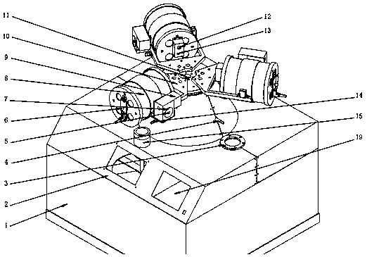
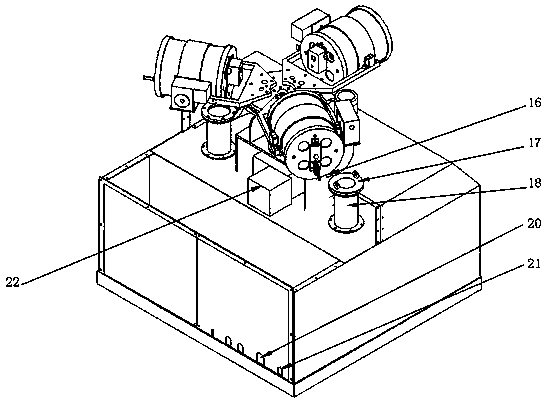
[0030] The heat treatment experimental device in this embodiment includes a cooling water tank 1, a body 2, a water quenching net 3, a furnace shaft 5, a furnace door 6, a turbine worm 7, a furnace body 8, a furnace body motor 9, a furnace body bracket 10, and a main shaft 11. Protective atmosphere inlet 12, thermocouple inlet 13, end quenching sample holder 15, oil quenching net bag 17, quenching oil pool 18, controller 19, cooling water inlet 20, cooling water outlet 21, furnace body support motor 22; body 2 is provided with a cooling water tank 1 underneath the body 2, a furnace body support motor 22 and a turbine reducer are provided on the upper surface of the body 2, the furnace body support motor 22 is connected to the turbine reducer, the output shaft of the turbine reducer is connected to the main shaft 11, and the main shaft 11 passes The flange is connected to the furnace body bracket 10; the furnace body bracket 10 is connected to the furnace body shaft 5 through the...

Embodiment approach 1

[0039] The device described in this embodiment is used for water quenching operation:

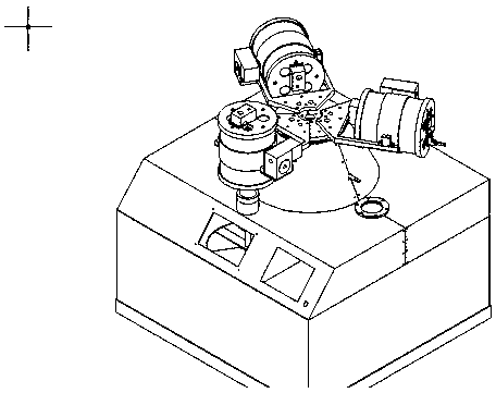
[0040] Load the sample, pass in the protective atmosphere, and heat up the furnace body 8. When it reaches the set temperature, heat preservation is performed. After the heat preservation is completed, the furnace body support motor 22 drives the main shaft 11 to rotate the furnace body 8 to the water quenching station. The furnace body motor 9 drives the furnace body 8 to rotate down 90 degrees. At this time, the furnace door is opened, and the sample automatically falls into the water quenching net 3 to complete the quenching process, and then the furnace body motor 9 drives the furnace body 8 to rotate 90 degrees in reverse. Return the furnace body 8 to its original position to complete the water quenching process (such as Figure 4 Shown).

Embodiment approach 2

[0042] The device described in this embodiment is used for oil quenching operations:

[0043] Load the sample, pass in the protective atmosphere, and heat up the furnace body 8. When the set temperature is reached, heat preservation is performed. After the heat preservation is completed, the furnace body support motor 22 drives the main shaft 11 to rotate the furnace body 8 to the oil quenching station. The furnace body motor 9 drives the furnace body 8 to rotate 90 degrees downwards. At this time, the furnace door is opened, and the sample automatically falls into the quenching oil pool 18 to complete the quenching process, and then the furnace body motor 9 drives the furnace body 8 to rotate 90 degrees in reverse. Return the furnace body 8 to its original position to complete the oil quenching process (such as Figure 5 Shown).


PUM


Abstract

The invention discloses a heat treatment experiment device and belongs to the field of material heat treatment and performance tests. The heat treatment experiment device mainly comprises a plurality of heating furnaces, a rotary mechanism, a quenching workbench, a normalization workbench, a tail end quenching workbench, a furnace body support rotary mechanism, a furnace body, a circulating cooling system and an atmosphere protection system. The rotary mechanism supports the heating furnaces and drives the heating furnaces to rotate along a spindle. Under driving of the spindle, the furnace body can rotate to be above the set workbench, meanwhile, under driving of the furnace body rotary mechanism, the furnace body can rotate by 90 degrees, and the process that samples from the insides of the heating furnaces are subjected to oil quenching, water quenching, normalization and tail end quenching is completed. Traditional manual operation is replaced, and thus danger and measuring errors caused by manual operation are avoided completely. Artificial intelligence software is installed on an upper computer connected to the heat treatment experiment device, estimation judgment and experiment result prediction can be conducted on the set experiment parameters, the local operation process can be simulated through a virtual laboratory, and thus misoperation in the operation process is reduced. The heat treatment experiment device has wide experiment teaching application prospects and further has the characteristics of simple operation, high efficiency, safety, water saving and the like at the same time.

Description

Technical field [0001] The invention relates to a heat treatment experimental device, belonging to the field of material heat treatment and performance testing. Background technique [0002] Metal heat treatment is one of the important processes in the mechanical manufacturing process. The quality of heat treatment directly determines the product quality and use performance of the workpiece. For this reason, the experimental teaching of heat treatment process is one of the compulsory courses for materials and mechanical students. Heat treatment of materials is divided into different processes according to different processes: normalizing, annealing, quenching, solution heat treatment, aging and other treatment methods. The treatment process requires the heating and insulation of the sample. For a long time, the heat treatment experiments of various universities and colleges have been Using box furnace or crucible furnace to heat the sample, there are problems such as high energy ...

Claims


Application Information

Patent Timeline
Patent Type & Authority Patents(China)
IPC IPC(8): C21D1/55
CPCC21D1/55
Inventor 傅强段云彪熊志坚韦聪赵光萍王欣悦胡劲翟又文姜晰
Owner KUNMING UNIV OF SCI & TECH
Why Eureka
Try Eureka