
Anti-inclining electric pole positioning device capable of being operated by one person
A positioning device and anti-tilt technology, applied to building types, buildings, towers, etc., can solve the problems of righting failure, broken poles, time-consuming and labor-intensive problems
- Summary
- Abstract
- Description
- Claims
- Application Information
AI Technical Summary
Problems solved by technology
Method used
Image

Examples
Embodiment Construction
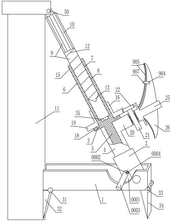
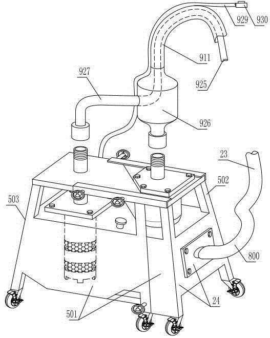
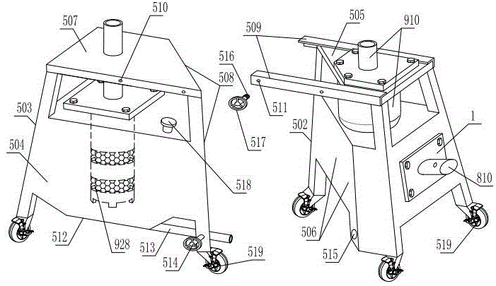
[0024] As shown in the figure, the pole anti-tilt positioning device that can be operated by one person includes a base 1 arranged horizontally. The longitudinal section of the base is U-shaped. There is a front limit device extending downward. A swing tube 2 capable of swinging back and forth is hinged in the support section of the base, and a support sleeve 4 is inserted into the swing tube. An inner rotating shaft 5 that can only rotate coaxially relative to the support sleeve is installed in the support sleeve. The upper end of the inner rotating shaft is coaxially fixed with an inner cylinder 6 extending out of the support sleeve. The inner cylinder inner wall is uniformly provided with an axially extending inner cylinder straight groove 7. Slot 8. It also includes a multi-purpose shaft 9 that is inserted and matched with the inner cylinder. The upper ring of the upper half of the peripheral wall of the multi-purpose shaft is provided with a shaft straight tooth 10 that...
PUM
 Abstract
Description
Claims
Application Information