A photovoltaic off-grid system

An off-grid, photovoltaic technology, applied in the direction of radio wave measurement systems, instruments, measuring devices, etc., can solve the problems of being easily stolen and unattended, and achieve the effect of preventing theft

Active Publication Date: 2018-02-09
兴储世纪科技股份有限公司
View PDF6 Cites 0 Cited by
  • Summary
  • Abstract
  • Description
  • Claims
  • Application Information

AI Technical Summary

Problems solved by technology

[0003] but figure 1 The locations of the various components of the off-grid system shown are scattered, and the controller 12, the inverter 14, and the battery pack 13 are generally placed indoors; since the photovoltaic components convert light energy into electrical energy, they must receive sunlight when working. Therefore, the photovoltaic modules must be placed outdoors or on the roof, and even some centralized photovoltaic off-grid systems will be installed in remote areas, unattended, and the modules are not working at night, which is easy to be stolen

Method used


Image

  • A photovoltaic off-grid system
  • A photovoltaic off-grid system
  • A photovoltaic off-grid system

Examples


Embodiment 1

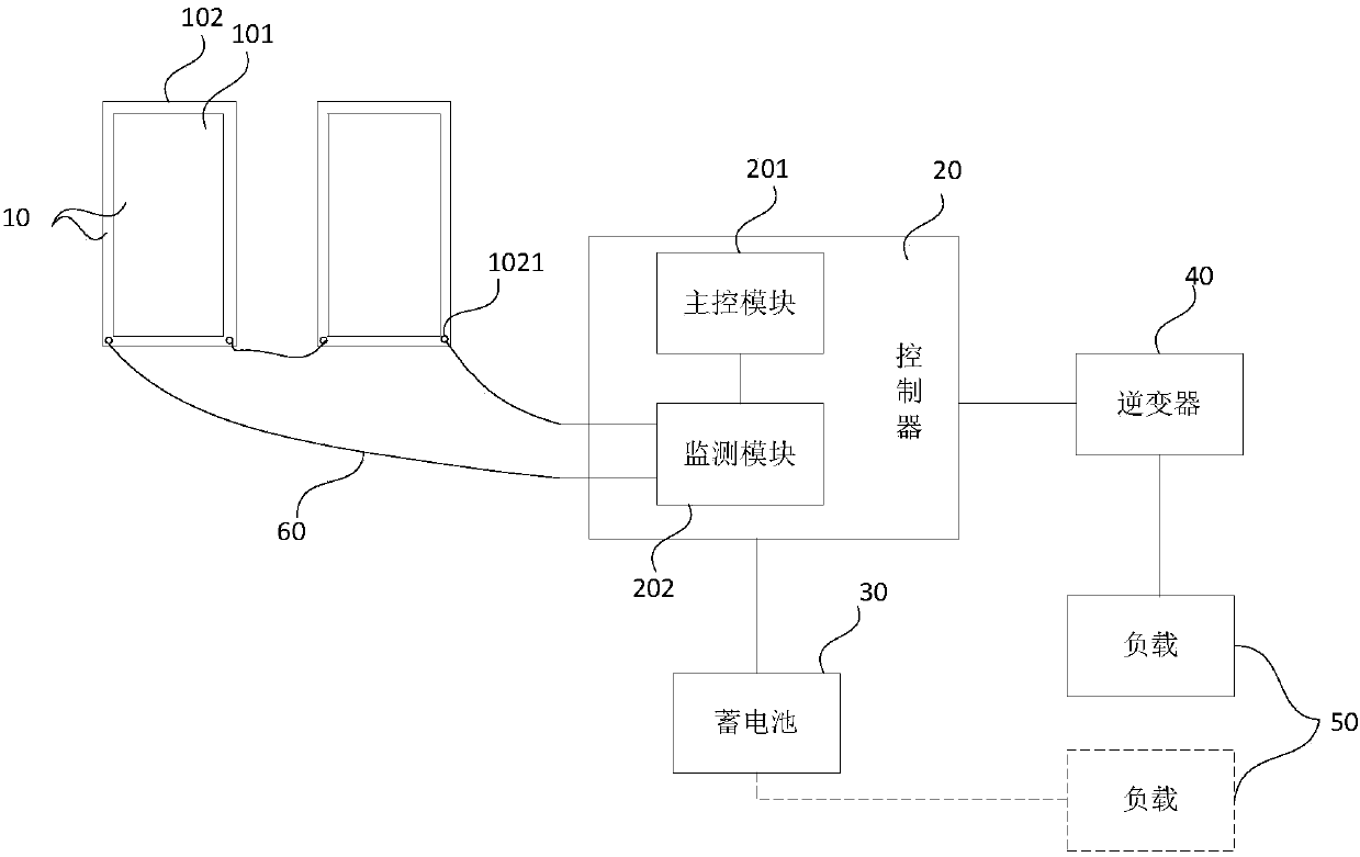
[0035] figure 2 It is a structural diagram of a photovoltaic off-grid system provided by Embodiment 1 of the present invention, such as figure 2 As shown, the system includes: at least one photovoltaic module 10, a controller 20, a storage battery 30, an inverter 40 and a load 50, the controller 20 is connected to the photovoltaic module 10, the storage battery 30 and the inverter 40 respectively, and the load 50 It is connected with the inverter 40 or the battery 30 , specifically, when the load 50 is a DC load, the load 50 is connected with the battery 30 , and when the load 50 is an AC load, the load 50 is connected with the inverter 40 .

[0036] Wherein, the photovoltaic assembly 10 includes a photovoltaic panel 101 and a metal frame 102; the controller 20 includes a main control module 201 and a monitoring module 202; the monitoring module 202 is connected to the metal frame 102 through a wire 60 to form a monitoring circuit; The component 10 monitors, and sends a mon...

Embodiment 2

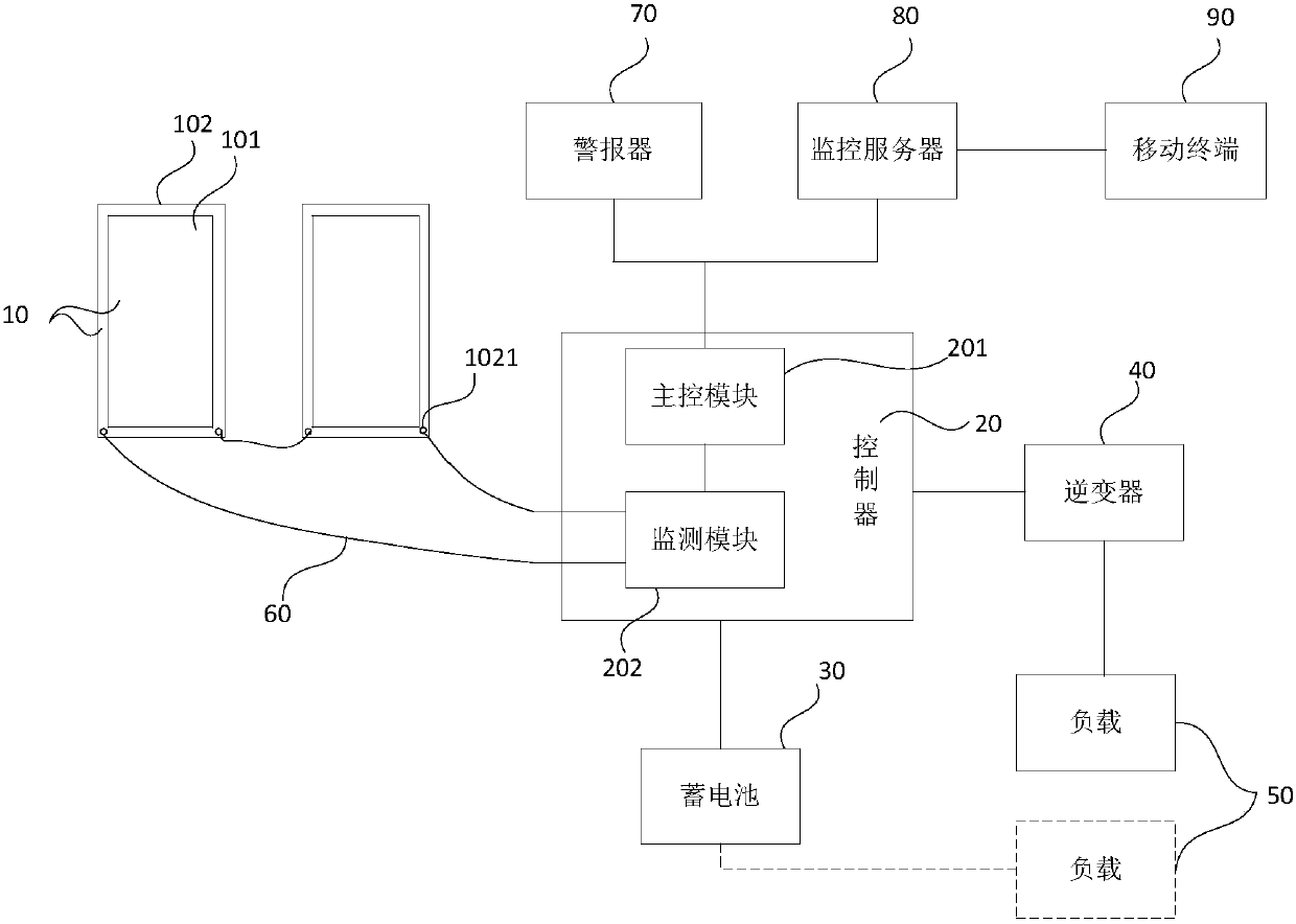
[0043] image 3 It is a structural diagram of an off-grid photovoltaic system provided by Embodiment 2 of the present invention. On the basis of the above embodiments, the controller and the monitoring module are optimized, and some components are added, such as image 3 As shown, the system includes: at least one photovoltaic module 10, a controller 20, a storage battery 30, an inverter 40, and a load 50; wherein, the photovoltaic module 10 includes a photovoltaic panel 101 and a metal frame 102; the controller includes a main control module 201 and the monitoring module 202; the monitoring module 202 is connected with the metal frame 102 through the wire 60 to form a monitoring circuit.

[0044] On the basis of the above-mentioned embodiments, the system further includes an alarm 70, and the alarm 70 is connected to the main control module 201; the main control module 201 is also used to receive the monitoring signal sent by the monitoring module 202, and process the monitorin...


PUM


Abstract

The invention discloses a photovoltaic off-grid system which comprises at least one photovoltaic assembly, a controller, a storage battery, an inverter and a load.The controller is connected with the photovoltaic assemblies, the storage battery and the inverter separately, and the load is connected with the inverter or the storage battery; each photovoltaic assembly comprises a photovoltaic panel and a metal frame; the controller comprises a main control module and a monitor module; the monitor module and the metal frames are connected through wires to form monitor loops; the monitor loops are used for monitoring the photovoltaic assemblies and sending monitoring signals to the main control module through the monitor module; the main control module is connected with the monitor module in the monitor loops and used for receiving the monitor signals sent by the monitor module and judging on-off of the monitor loops according to the monitor signals to judge whether the photovoltaic assemblies are moved or not.According to the photovoltaic off-grid system, whether the photovoltaic assemblies are moved or not can be monitored, and therefore the photovoltaic assemblies can be prevented from being stolen.

Description

technical field [0001] The invention relates to the technical field of photovoltaic power generation, in particular to a photovoltaic off-grid system. Background technique [0002] Solar photovoltaic power generation system, as one of many solar energy resources, has been widely used in people's lives today. Photovoltaic off-grid system is a device that uses solar energy to generate electricity. Such as figure 1 As shown, the existing photovoltaic off-grid system generally consists of a photovoltaic module 11, a controller 12 connected to the photovoltaic module 11, a battery pack 13 connected to the controller 12, an inverter 14 connected to the controller 12, and a load 15, etc. Composition, wherein the load includes AC load 16 and DC load 17. The photovoltaic module converts solar energy into electric energy when there is light, and charges the battery pack 13 through the controller 12 ; when there is no light, the battery pack 13 supplies power to the AC load 16 throu...

Claims


Application Information

Patent Timeline
Patent Type & Authority Patents(China)
IPC IPC(8): G01V3/02
CPCG01V3/02
Inventor 钱立伟邢帅
Owner 兴储世纪科技股份有限公司
Why Eureka
Try Eureka