
Shaft sleeve and fastening ring positioning assembly

A technology of positioning components and fastening rings, applied in the direction of couplings, rigid shaft couplings, mechanical equipment, etc., can solve the problems of increasing manufacturing costs, complicated assembly, etc., and achieve the effect of good fixation and avoidance of movement.

Active Publication Date: 2016-08-10
苏州威富达精密机械制造有限公司
View PDF8 Cites 0 Cited by
  • Summary
  • Abstract
  • Description
  • Claims
  • Application Information

AI Technical Summary

Problems solved by technology

[0002] The connecting shaft is an important part of the mechanical parts. It is widely used in various fields. When the shaft is assembled, sometimes it needs to be used with a shaft sleeve. The shaft sleeve needs to be connected and fixed with the shaft. The existing connection methods are mostly screws, threads, etc. , the assembly is more cumbersome, and it is necessary to process threads or threaded holes on the parts, which increases the manufacturing cost

Method used


Image

  • Shaft sleeve and fastening ring positioning assembly

Examples


Embodiment Construction

[0011] The present invention is described below in conjunction with accompanying drawing.

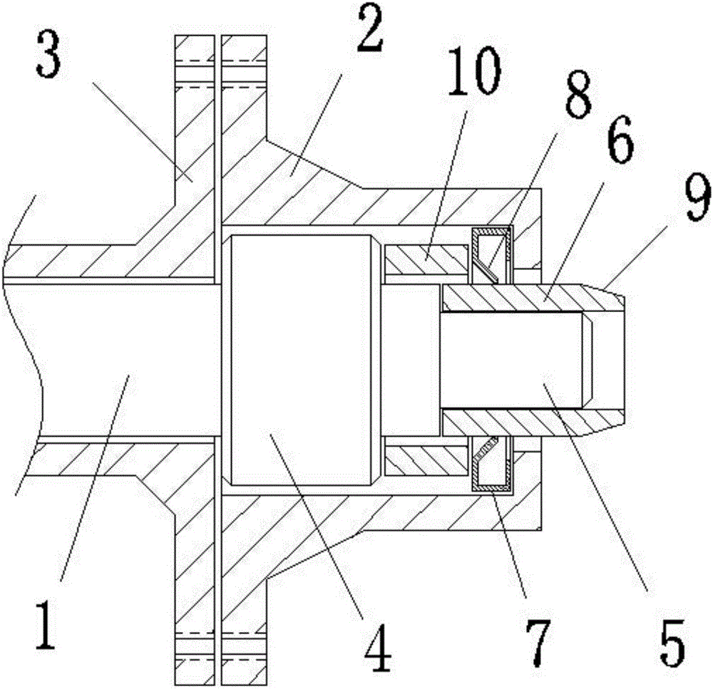
[0012] Such as figure 1 As shown, a shaft sleeve fastening ring positioning assembly according to the present invention includes a shaft body 1, a front connecting sleeve 2 and a rear connecting sleeve 3; the front end of the shaft body 1 is provided with a pillow block 4, and the The front end is provided with a shaft head 5, the shaft head 5 is provided with a shaft sleeve 6, the outer diameter of the shaft sleeve 6 is equal to the diameter of the shaft body 1, and the front end of the shaft sleeve 6 is provided with a transition bevel 9; the rear connecting sleeve 3 and The shaft body 1 is matched with the pillow block 4, the front connecting sleeve 2 is matched with the pillow block 4 and the shaft sleeve 6, and the front connecting sleeve 2 and the rear connecting sleeve 3 are connected and fixed by connecting pieces, which are generally bolts; the front connecting sleeve 2 A fast...


PUM


Abstract

The invention discloses a shaft sleeve and fastening ring positioning assembly. The shaft sleeve and fastening ring positioning assembly comprises a shaft body, a front connecting sleeve and a rear connecting sleeve. The shaft body is provided with a plummer block and a shaft head, and the shaft head is provided with a shaft sleeve. The front connecting sleeve and the rear connecting sleeve are connected and fixed through a connecting piece. A fastening ring and a positioning ring are arranged in the front connecting sleeve. The fastening ring is located at the front end of the front connecting sleeve. The positioning ring is arranged between the fastening ring and the plummer block. A ring arm bent forwards is arranged on the inner circle of the fastening ring, and the end portion of the ring arm is in interference fit with the shaft sleeve. When the front connecting sleeve and the rear connecting sleeve are connected and fixed, the front connecting sleeve drives the fastening ring to move towards the rear end of the shaft sleeve from the front end of the shaft sleeve, the end portion of the front connecting sleeve and the shaft sleeve are in an interference fit state, and therefore the shaft sleeve is clamped on the shaft head under the interaction of the fastening ring and the shaft sleeve, and a very good fixing function is achieved for the shaft sleeve. Meanwhile, due to the fact that the positioning ring is arranged between the fastening ring and the plummer block, the fastening ring can be clamped at the front end of the front connecting sleeve through the positioning ring, and moving of the fastening ring is avoided.

Description

technical field [0001] The invention relates to a shaft sleeve fastening ring positioning assembly. Background technique [0002] The connecting shaft is an important part of the mechanical parts. It is widely used in various fields. When the shaft is assembled, sometimes it needs to be used with a shaft sleeve. The shaft sleeve needs to be connected and fixed with the shaft. The existing connection methods are mostly screws, threads, etc. , the assembly is relatively cumbersome, and threads or threaded holes need to be processed on the parts, which increases the manufacturing cost. Contents of the invention [0003] In view of the above-mentioned technical problems, the object of the present invention is to propose a shaft sleeve fastening ring positioning assembly. [0004] The technical solution of the present invention is realized in the following way: a shaft sleeve fastening ring positioning assembly includes a shaft body, a front connecting sleeve and a rear connec...

Claims


Application Information

Patent Timeline
IPC IPC(8): F16D1/076
CPCF16D1/076
Inventor 何兆东
Owner 苏州威富达精密机械制造有限公司
Learn More