Light source device and vehicle lamp

A technology of a light source device and a housing, which is applied in the directions of light sources, headlights, road vehicles, etc., can solve problems such as difficult contact states, and achieve the effect of suppressing sliding wear

Active Publication Date: 2018-06-15
KOITO MFG CO LTD
View PDF4 Cites 0 Cited by
  • Summary
  • Abstract
  • Description
  • Claims
  • Application Information

AI Technical Summary

Problems solved by technology

[0005] However, according to the conventional light source device 51, since the FPC 52 is connected to the connection conductor 56 inside the casing 55, it is difficult to visually confirm the power receiving unit 54 on the LED 53 side and the power supply unit 57 on the external power supply side from the outside of the casing 55. contact status
In addition, since the FPC 52 is not fixed inside the housing 55, micro-sliding wear occurs at the contact portion between the power receiving unit 54 and the power feeding unit 57 due to external vibrations or shocks, which may cause flickering or non-lighting of the light source.

Method used


Image

  • Light source device and vehicle lamp
  • Light source device and vehicle lamp
  • Light source device and vehicle lamp

Examples


Embodiment Construction

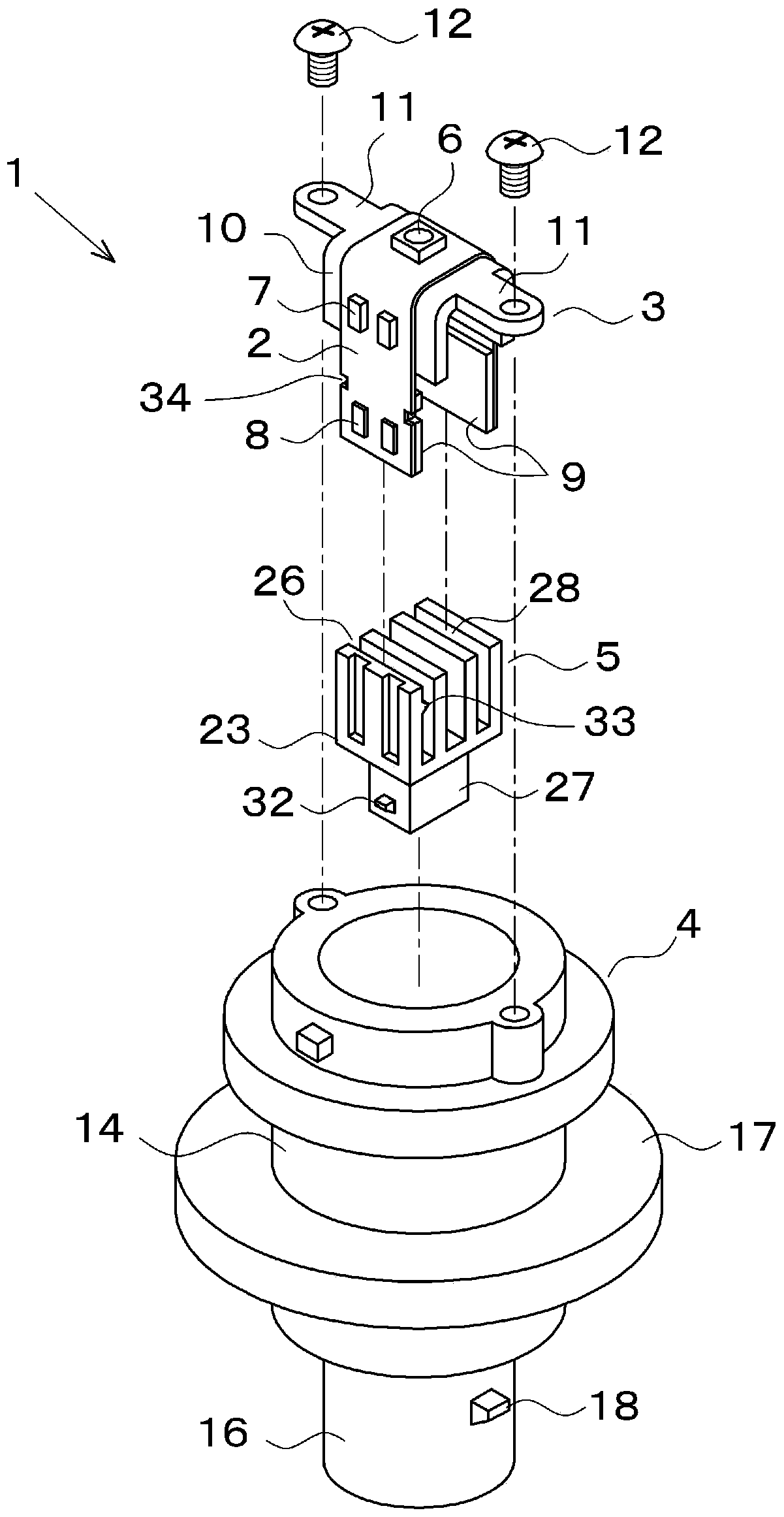
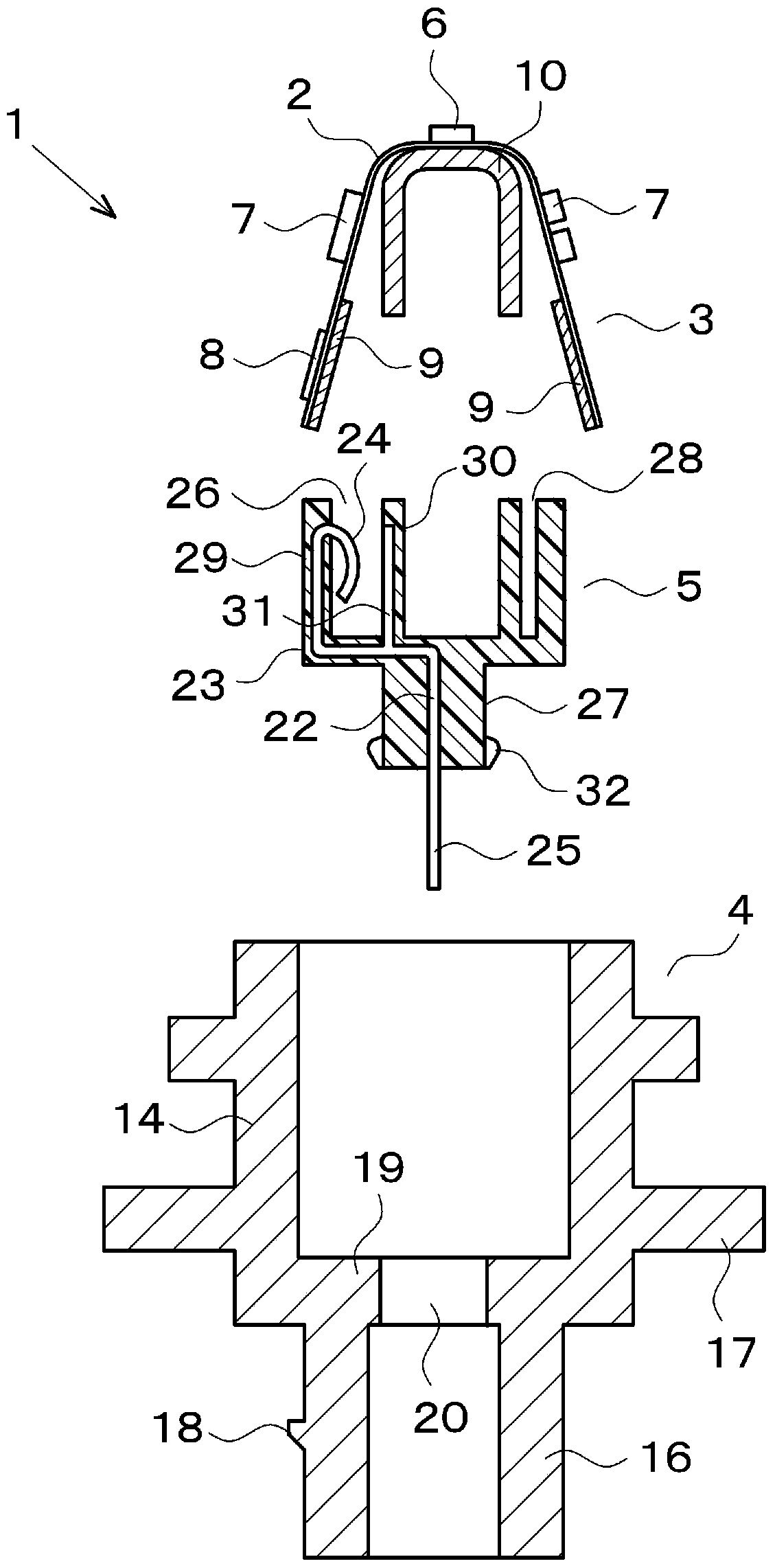
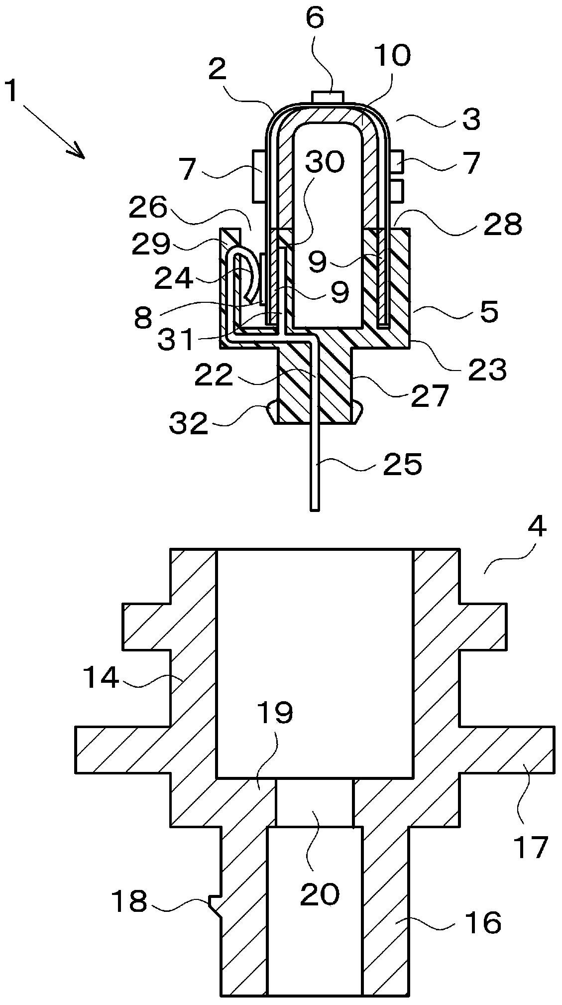
[0058] Next, an embodiment in which the present invention is implemented as a light source device for a vehicle lamp will be described with reference to the drawings. In the following embodiments, various limitations are made on constituent elements, types, combinations, shapes, relative arrangements, etc., but these are merely examples, and the present invention is not limited thereto.

[0059] Such as figure 1 , figure 2 As shown, the light source device 1 of this embodiment is composed of a wiring base 3 provided with an FPC 2 , a case 4 for accommodating the wiring base 3 , and an adapter 5 for assembling the wiring base 3 to the housing 4 . The FPC 2 is provided with a control circuit element 7 for controlling the LED 6 as a light emitting element, a control circuit element 7 for the LED 6 , a power receiving unit 8 for receiving power from the LED 6 , and reinforcing plates 9 for increasing rigidity at both ends of the FPC 2 . The wiring base 3 includes a metal light...


PUM


Abstract

The invention provides a light source device capable of visually confirming the contact state between a power receiving part on a light emitting element side and a power supply part on an external power supply side, and preventing sliding wear of a contact part. A light source device (1) comprises a wiring base (3) provided with an LED (6) and a power receiving part (8), a housing (4) for housing the wiring base (3), and a connector (5) for assembling the wiring base (3) with the housing (4). The connector (5) is provided with a connection conductor (22) for connecting a power receiving part (8) of a wiring base (3) to an external power source, a first holding portion (26) keeping a power reception portion (24) on the power supplying side in contact with the power receiving part (8), and a second holding portion (27) for keeping a power supply side end (25) of the connection conductor (22) in the insertion hole (20) of the housing (4). The first holding part (26) includes an engagement wall (29) and a clamping wall (30).

Description

technical field [0001] The present invention relates to a light source device in which a wiring base provided with a light emitting element and a power receiving unit is housed inside a case, and a vehicle lamp equipped with the light source device. Background technique [0002] Conventionally, a light source device is known in which a light-emitting element such as an LED and its control circuit are mounted on an FPC (flexible printed circuit board) and the FPC is accommodated inside a case. For example, Figure 6 The shown conventional light source device 51 is configured by disposing the LED 53 and the power receiving unit 54 on the FPC 52, embedding the connection conductor 56 in the housing 55 made of insulating material, inserting the FPC 52 into the inside of the housing 55, so that the power receiving unit 54 is in contact with the power supply part 57 of the connection conductor 56, and electric power is supplied to LED53 from an external power supply through the co...

Claims


Application Information

Patent Timeline
Patent Type & Authority Patents(China)
IPC IPC(8): F21S41/141F21S43/14F21S45/47F21V23/06F21V29/85F21W107/10F21Y115/10
CPCF21S43/00F21V23/06F21V29/85F21W2107/10
Inventor 伊东范明
Owner KOITO MFG CO LTD
Why Eureka
Try Eureka