Oil seal

An oil seal and sealing lip technology, which is applied to engine components, engine seals, mechanical equipment, etc., can solve the problem of no reverse thread part, etc., and achieve the effects of increasing contact width, convenient leakage and low torque.

Active Publication Date: 2013-08-28
NOK CORP
View PDF8 Cites 0 Cited by
  • Summary
  • Abstract
  • Description
  • Claims
  • Application Information

AI Technical Summary

Problems solved by technology

[0006] Also, although the technology of providing an intermediate surface between the sealing fluid side slope and the anti-sealing fluid side slope is described in the following patent document 2, this prior art does not provide a reverse thread portion on the intermediate surface.

Method used


Image

  • Oil seal
  • Oil seal
  • Oil seal

Examples


Embodiment

[0056] Embodiments of the present invention will be described below with reference to the drawings.

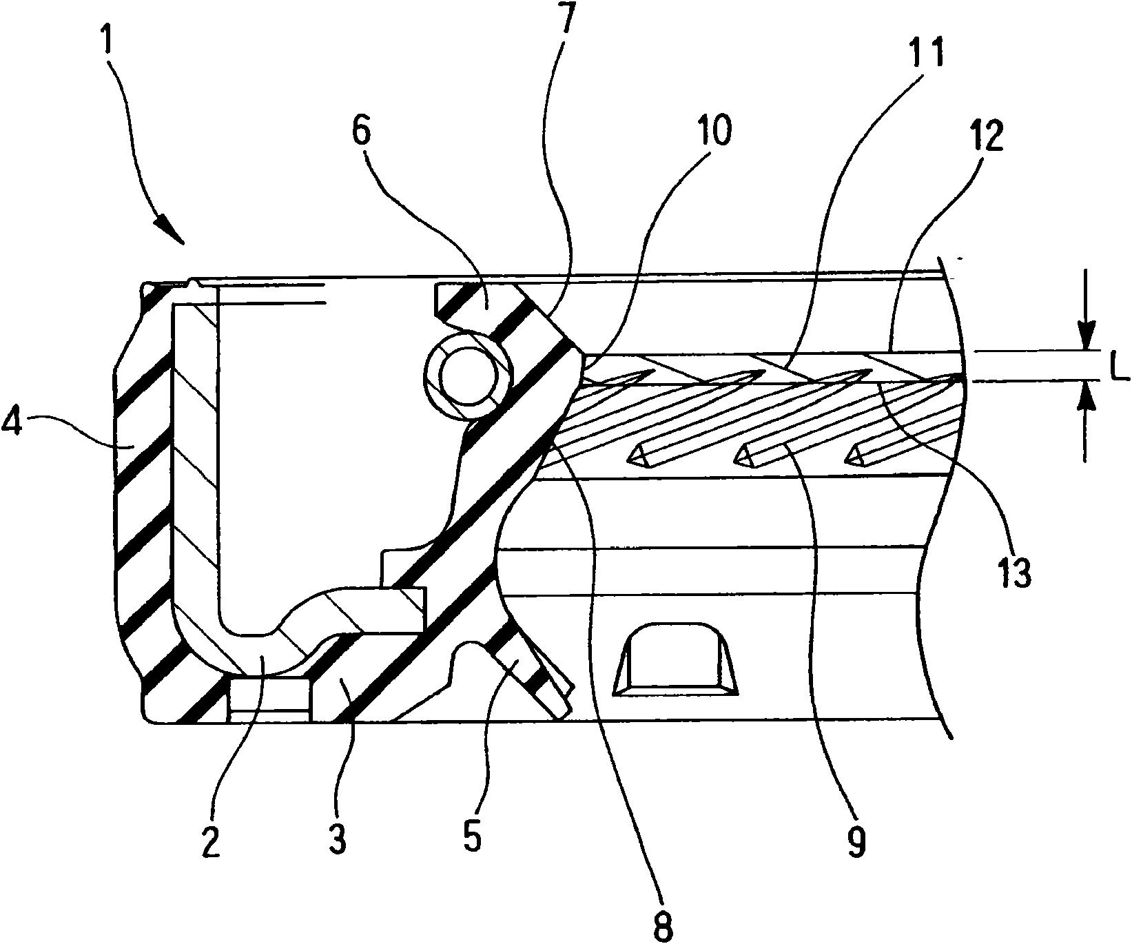
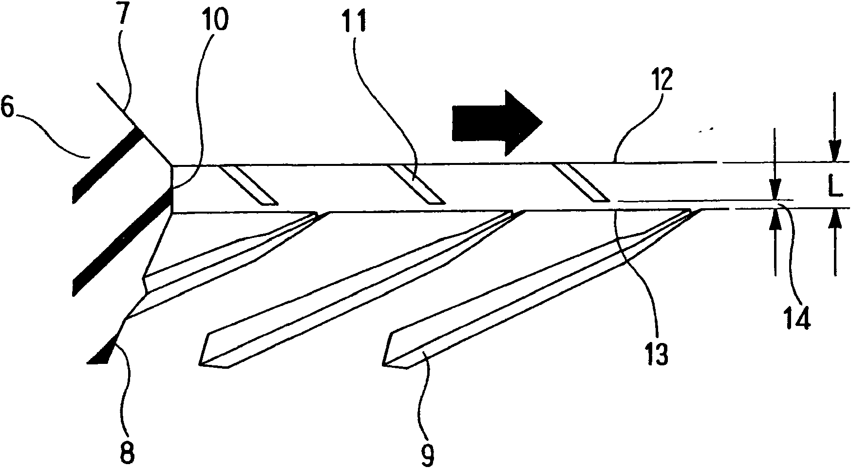
[0057] figure 1 A sectional view of main parts of the oil seal 1 according to the embodiment of the present invention is shown, and the oil seal 1 of the present embodiment is constituted as follows.

[0058] That is, first, the seal lip 6 is provided, and the seal lip 6 is in close contact with the shaft slidably together with the outer peripheral seal portion 4 and the dustproof lip 5 through the rubber elastic body 3 adhered (vulcanized) to the metal ring 2. (Cooperating components, not shown) on the front end sliding part of the sealing lip 6, the sealing fluid side slope 7 and the anti-sealing fluid side slope 8 are arranged, and on the latter anti-sealing fluid side slope 8, a rotary The threaded part (positive threaded part) 9 that presses back the sealing fluid is realized by the suction action at the time. The threaded portion 9 is composed of a plurality of helica...


PUM


Abstract

An oil seal (1) has a seal lip (6) in slidable intimate contact with the circumferential surface of a mating member, a slope (7) on the side of sealed fluid and a slope (8) on the side opposite to the sealed fluid that are provided on the seal lip (6), and a screw section (9) provided on the slope (8) on the side opposite to the sealed fluid and performing a function of pushing back the sealed fluid by a pumping effect induced by rotation of the mating member. The oil seal (1) has low torque characteristics based on fluid lubrication, and such characteristics are achieved by increasing the thickness of an oil film on sliding surfaces. An intermediate surface (10) is provided between the slopes (7, 8), and an oppositely threaded screw section (11) for performing a function of sucking the sealed fluid by a pumping effect induced by rotation of the mating member is provided on the intermediate surface (10). The oppositely threaded screw section (11) on the intermediate surface (10) is provided in such a way that the screw section (11) does not reach the boundary (13) between the intermediate surface (10) and the slope (8), and this provides a threadless region that lies in the entire circumference between the screw section (11) and the boundary (13) and is in intimate contact with the circumferential surface of the mating member.

Description

technical field [0001] The present invention relates to an oil seal as a type of sealing device. The oil seal of the present invention is used, for example, in fields related to automobiles, or in fields such as general machinery. Background technique [0002] In oil seals, lower torque is generally required to suppress sliding wear of the seal lip. As a means of lowering the torque, studies have been conducted on lowering the coefficient of friction, such as reducing the pressing force, changing the material, and modifying the surface (such as fluororesin coating) due to the reduction in the cross-section of the seal lip. Torque reduction is considered to achieve low torque based on fluid lubrication by thickening the oil film on the sliding surface. [0003] As existing technology, such as Figure 6 As shown, threaded parts 54, 55 are respectively provided on the sealing fluid side slope 52 and the anti-sealing fluid side slope 53 of the sealing lip 51, and the sealing f...

Claims


Application Information

Patent Timeline
Patent Type & Authority Patents(China)
IPC IPC(8): F16J15/32F16J15/3244
CPCF16J15/3244F16J15/324
Inventor 松井宏树谷田昌幸水田裕贤古山秀之吉川贤佐藤祐树
Owner NOK CORP
Why Eureka
Try Eureka