Sealed chain

A chain and rigid sealing technology, applied in the transmission chain and other directions, can solve the problems of reduced sealing effect, reduced sealing function, loss of elastic sealing parts, etc., to achieve the effect of maintaining the sealing effect and suppressing sliding wear

Inactive Publication Date: 2006-11-01
TSUBAKIMOTO CHAIN CO
View PDF2 Cites 0 Cited by
  • Summary
  • Abstract
  • Description
  • Claims
  • Application Information

AI Technical Summary

Problems solved by technology

Therefore, fine particles are easy to enter, and the effect of sufficient sealing cannot be achieved
Moreover, because in the double-seal type sealing structure, the two elastic parts that realize the sealing function directly contact the inner plate or the outer plate, so the elastic sealing part is in sliding contact with the plate during the bending movement of the chain, and the elastic sealing part is gradually worn, so that the Reduced sealing function
Moreover, since the outer seal ring is exposed to the outside, due to collision with items in the sliding contact chain (such as items conveyed on a conveyor chain) or a change in the space between the pin and the bush, the outer seal ring is in contact with the pin Sliding in the vertical direction (radial direction), and the elastic sealing part sandwiched between the outer sealing ring and the inner plate is worn due to wear with the inner plate, thereby reducing the sealing effect

Method used


Image

  • Sealed chain
  • Sealed chain
  • Sealed chain

Examples


Embodiment Construction

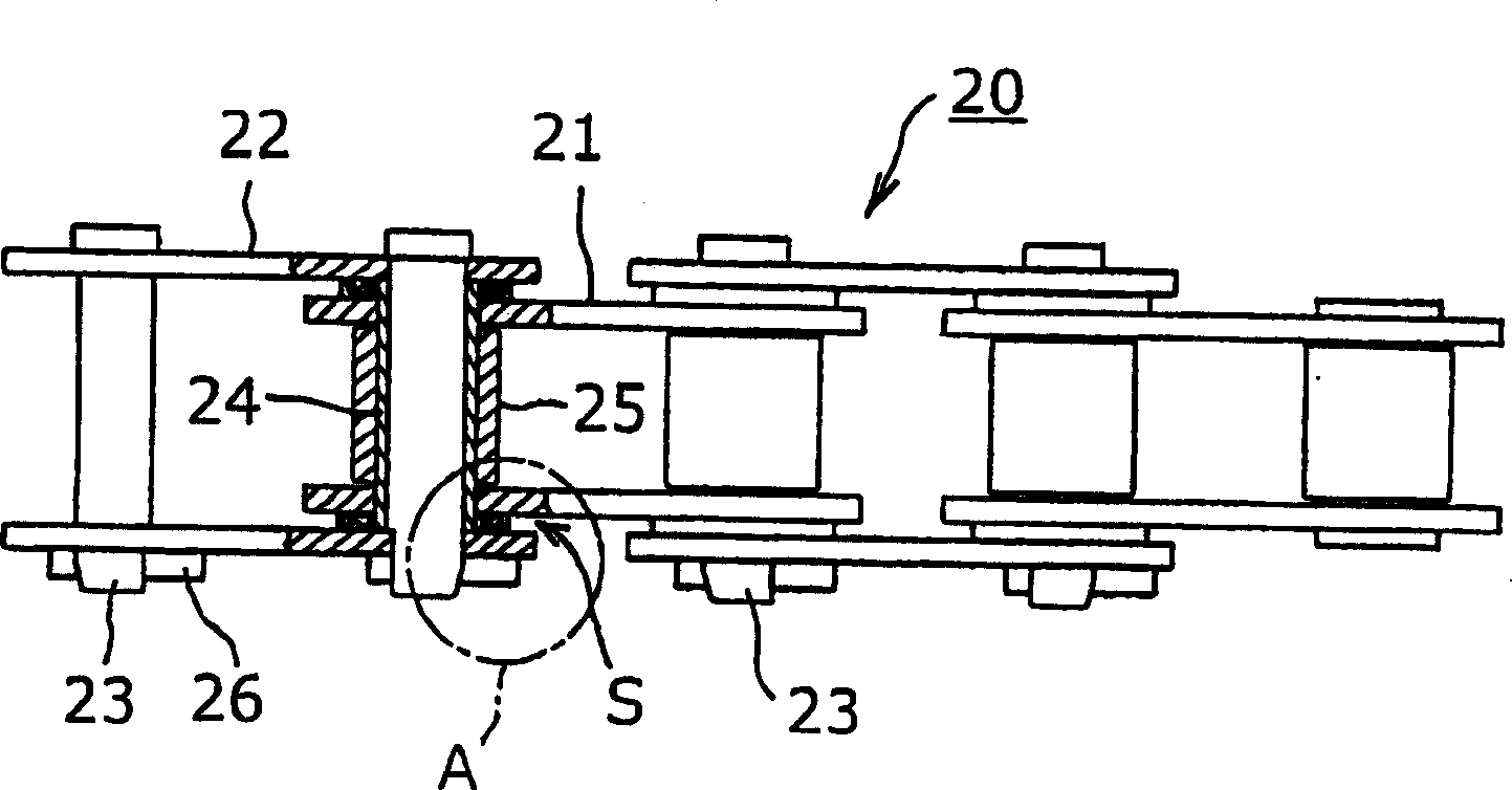
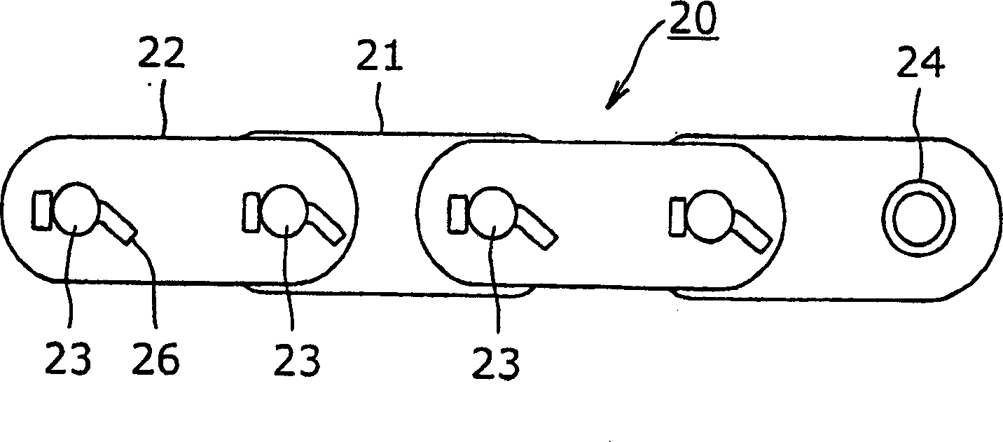
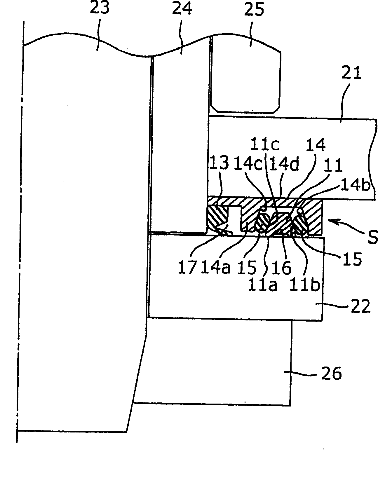
[0015] A sealing chain of an embodiment of the present invention will be described below with reference to FIGS. 1 and 2 . Specifically, Fig. 1 shows the overall structure of the sealing chain 20, figure 2 is an enlarged cross-sectional view of the seal structure that is characteristic of the seal chain of Example 1 of the present invention. figure 2 Corresponds to the portion shown by the dotted circle A in FIG. 1 .

[0016] The sealed chain 20 is a chain with a plurality of connecting components connected. In the sealed chain 20, one of the adjacent connecting components includes a pair of inner plates 21, 21 spaced apart along a direction perpendicular to the longitudinal direction of the chain, and a hollow cylindrical shape press-fitted in the pair of inner plates. Bushing 24; the other of this adjacent connection assembly comprises a pair of outer plates 22, 22 spaced apart along the direction perpendicular to the longitudinal direction of the chain at the outer side...


PUM


Abstract

A sealing chain that suppresses wear between sealing parts and maintains high sealing performance during long-term use. The sealing chain comprises a first rigid sealing part (14) between the inner plate (21) and the outer plate (22), the back side of the first rigid sealing part contacts the inner plate (21), and the first rigid sealing part ( 14) has a trapezoidal cross-section groove on the front surface of the outer plate (22); the second trapezoidal cross-section of the trapezoidal cross-section arranged in a manner spaced apart from the inner wall of the trapezoidal cross-section groove in the trapezoidal cross-section groove of the first rigid sealing member (14) Two rigid sealing parts (11), the back side of the second rigid sealing part contacts the outer plate (22); two elastic material made between the opposite side walls of the trapezoidal section groove and the second rigid sealing part of trapezoidal section An annular sealing member (15).

Description

technical field [0001] The present invention relates to a sealing chain, which has an annular sealing part made of elastic material for preventing the lubricating oil (such as grease) sealed between the outer peripheral surface of the pin and the inner peripheral surface of the bush from leaking outwards, At the same time foreign matter is prevented from entering the gap between the outer peripheral surface of the pin and the inner peripheral surface of the bush. Background technique [0002] The sealing chain generally has a sealing structure A in the space S between the inner plate 21 and the outer plate 22 . As the sealing structure, various types of sealing structures have been proposed, such as Figure 1(a) and 1(b) shown. For example, if image 3 As shown, an inner seal ring 34 and an outer seal ring 31 are installed between the inner plate 21 and the outer plate 22 and adjacent the outer peripheral surface of the edge of the bush loosely fitted on the pin 23 . Nec...

Claims


Application Information

Patent Timeline
Patent Type & Authority Patents(China)
IPC IPC(8): F16G13/02
Inventor 藤原诚
Owner TSUBAKIMOTO CHAIN CO
Why Eureka
Try Eureka