[0044] Attached to the following Figure 1-4 This application will be described in further detail.
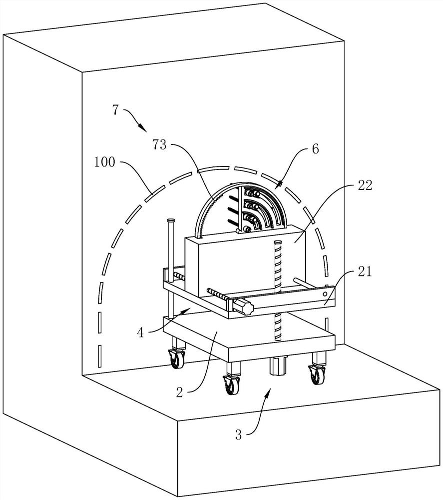
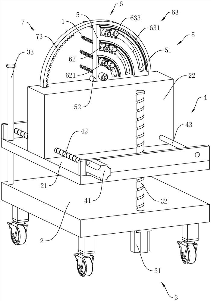
[0045] The embodiments of the present application disclose a device for controlling over-under-excavation of large-section tunnels in complex strata.
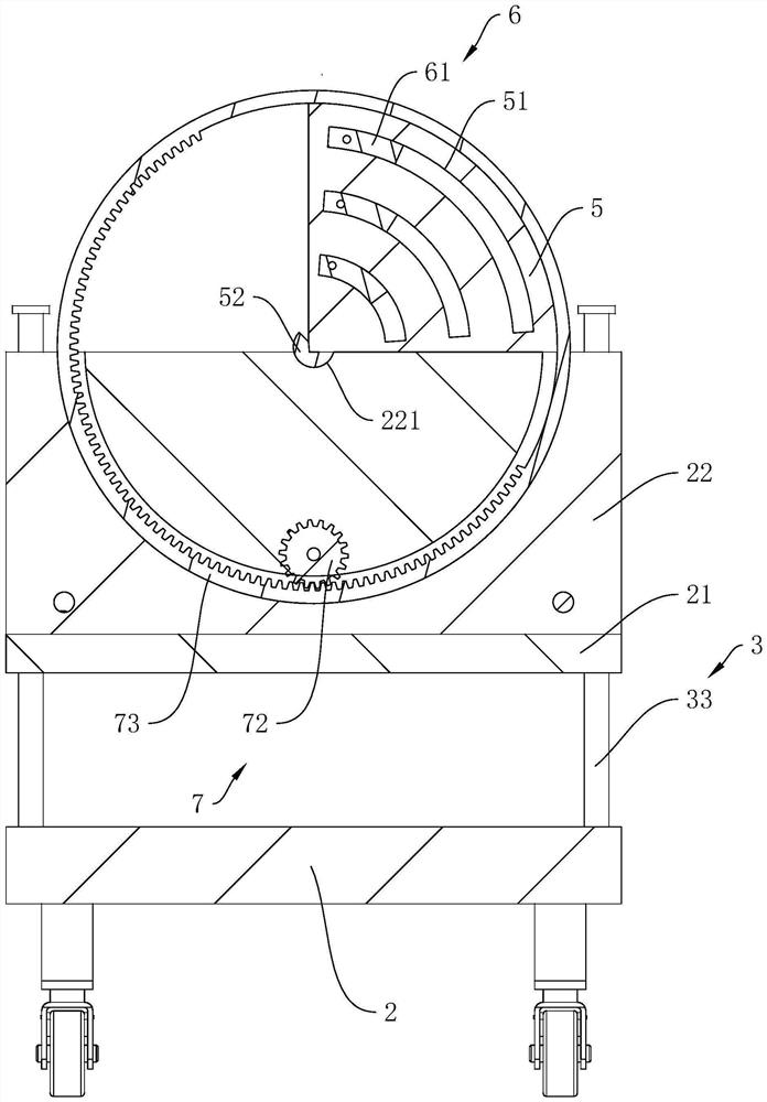
[0046] refer to figure 1 and figure 2 , a large-section tunnel over-under-excavation control device in complex strata includes a base 2 arranged on the ground, a horizontally arranged lifting plate 21 is arranged on the base 2, and a lifting assembly for driving the lifting plate 21 to vertically lift is arranged on the base 2 3. An adjustment block 22 is provided on the upper surface of the lifting plate 21 to slide, and a power assembly 4 for driving the adjustment block 22 to slide horizontally is arranged between the lifting plate 21 and the adjustment block 22 .
[0047] refer to figure 2 , the adjusting block 22 is rotatably connected with the protective plate 5, between the adjusting block 22 and the protective plate 5 there is a rotating assembly 7 for driving the protective plate 5 to rotate, the cross-section of the protective plate 5 is a quarter circle, and the cross-section of the protective plate 5 is a quarter circle. The center of the circle is located on the adjustment block 22, the protective plate 5 is rotatably connected with a plurality of rotating augers 1, the axis of the rotating auger 1 is arranged perpendicular to the wall surface, and the side wall of the protective plate 5 facing the wall has a plurality of arcuate openings. There is a guide hole 51 for the rotating auger 1 to move, and an adjusting mechanism 6 for driving the rotating auger 1 to rotate and move in the guide hole 51 is provided between the protective plate 5 and the rotating auger 1 .
[0048] The base 2 is attached to the wall, and the infrared rays point to the position on the wall to be excavated. The lifting component 3 adjusts the lifting plate 21 to a specified height. The adjustment mechanism 6 adjusts the plurality of rotating augers 1 to a specified shape. The rotating component 7 will rotate The auger 1 rotates to the designated position, the adjusting mechanism 6 drives the rotating auger 1 to rotate, and the power component 4 drives the rotating auger 1 to move toward the wall through the adjusting block 22, which improves the stability of the path during hole excavation, thereby reducing the tunnel overload. Probability of undermining.
[0049] refer to figure 2 The lift assembly 3 includes a lift motor 31 fixed on the base 2, a lift screw 32 rotatably connected to the base 2, and a fixed rod 33 fixed on the base 2. The output shaft of the lift motor 31 is coaxial with the lift screw 32 For fixed connection, the lifting screw 32 is arranged through the lifting plate 21 and is threadedly matched with the lifting plate 21 , the lifting screw 32 is vertically arranged, the fixing rod 33 is arranged through the lifting plate 21 and is slidably connected with the lifting plate 21 , and the lifting screw 32 is parallel to the fixing rod 33 Setting; turn on the lift motor 31, the output shaft of the lift motor 31 drives the lift screw 32 to rotate, the lift screw 32 drives the lift plate 21 to slide along the length of the fixed rod 33, realizes the smooth lift of the lift plate 21, and improves the rotating auger 1 lift stability.
[0050] refer to figure 2 , the power assembly 4 includes a power motor 41 fixed on the lift plate 21, a power screw 42 rotatably connected to the lift plate 21 and a guide rod 43 fixed on the lift plate 21, the output shaft of the power motor 41 and the power screw 42 are coaxially connected, the power screw 42 penetrates through the adjustment block 22 and is threaded with the adjustment block 22, the power screw 42 is arranged horizontally, the guide rod 43 penetrates the adjustment block 22 and is slidably connected with the adjustment block 22, and the guide rod 43 is parallel to the power screw 42 Setting; turn on the power motor 41, the output shaft of the power motor 41 drives the power screw 42 to rotate, and the power screw 42 drives the adjustment block 22 to slide along the length direction of the guide rod 43, so as to realize the horizontal sliding of the adjustment block 22 and improve the rotation twist. Long 1 stability when drilling.
[0051] refer to image 3 and Figure 4 , the rotating assembly 7 includes a rotating motor 71 fixed in the adjusting block 22, a rotating gear 72 rotatably connected in the adjusting block 22 and a gear ring 73 rotatably connected in the adjusting block 22, the output shaft of the rotating motor 71 and the rotating gear 72 are coaxially connected, the rotation axis of the rotating gear 72 and the rotation axis of the gear ring 73 are both arranged parallel to the guide rod 43, and the circumferential inner wall of the gear ring 73 is fixedly connected with the circumferential outer wall of the protective plate 5, so that the protective plate 5 It is more stable during rotation, which improves the stability of the position adjustment of the rotating auger 1; a fixing member 52 is fixed coaxially at the rotation axis of the protective plate 5, the bottom wall of the fixing member 52 is arranged in an arc shape, and the adjusting block 22 is provided with a The abutting groove 221 for inserting the fixing piece 52 increases the contact area between the protective plate 5 and the adjusting block 22 , and improves the working stability of the rotating auger 1 .
[0052] refer to image 3 and Figure 4 , the adjustment mechanism 6 includes a sliding block 61, a driving motor 62 and an adjustment assembly 63 for driving the sliding block 61 to slide along the length direction of the guide hole 51. The sliding block 61 corresponds to the guide hole 51 one-to-one. 61 is limited in the guide hole 51 and slides along the length direction of the guide hole 51, the rotating auger 1 is rotatably connected to the sliding block 61, and the driving motor 62 is fixed on the sliding block 61 and is the same as the rotating auger 1. The shaft is fixedly connected, and the driving motor 62 drives the rotating auger 1 to rotate.
[0053] refer to Figure 4 , the adjustment assembly 63 corresponds to the guide hole 51 one by one, the adjustment assembly 63 includes an arc-shaped rack 631, an adjustment gear 632 and an adjustment motor 633, the arc-shaped rack 631 is fixed on the protective plate 5, and the arc-shaped rack 631 is attached Near the corresponding guide hole 51 , the adjusting gear 632 is rotatably connected to the sliding block 61 , the adjusting motor 633 is fixed on the sliding block 61 , and the output shaft of the adjusting motor 633 is fixed coaxially with the adjusting gear 632 .
[0054] The adjusting motor 633 drives the sliding block 61 to adjust the position along the length direction of the arc-shaped rack 631 through the adjusting gear 632, which improves the variability of the positions of the multiple rotating augers 1. The dragon 1 can be adjusted and fixed according to the hole route that needs to be dug on the wall, which adapts to the variability of the actual construction and improves the applicability of the rotating auger 1.
[0055] refer to Figure 4 , the drive motor 62 is fixed with a receiver 621 for receiving infrared rays, the receiver 621 is fixed on the side of the drive motor 62 away from its output shaft, and the receiver 621 and the output shaft of the drive motor 62 are coaxially arranged; On the wall, the position of the rotating auger 1 is adjusted so that infrared rays are projected on the receiver 621. The receiver 621 improves the excavation accuracy of the rotating auger 1, and further reduces the probability of over- or under-digging of the tunnel.
[0056] The implementation principle of an over-under-excavation control device for a large-section tunnel in a complex stratum in an embodiment of the present application is as follows: the base 2 is attached to the wall and fixed on the wall, the lifting motor 31 is turned on, and the output shaft of the lifting motor 31 drives the lifting screw 32 Rotating, the lifting screw 32 drives the lifting plate 21 to rise to the specified height along the length direction of the fixed rod 33; the adjusting motor 633 drives the sliding block 61 to adjust the position along the length direction of the arc-shaped rack 631 through the adjusting gear 632, and simultaneously rotates the motor 71 By rotating the gear 72, the gear ring 73 is driven to rotate, and the gear ring 73 drives the protective plate 5 to rotate to the designated position, so that the infrared rays are projected on the receiving member 621, and the driving motor 62 is turned on. 41. The output shaft of the power motor 41 drives the power screw 42 to rotate, and the power screw 42 drives the adjustment block 22 to move towards the wall, and the rotating auger 1 digs the position of the infrared projection, which improves the stability of the path during hole excavation, thereby reducing the The probability of over-under-excavation of the tunnel.
[0057] The embodiment of the present application also discloses a method for controlling over-under-excavation of a large-section tunnel in a complex stratum, comprising the following steps:
[0058] S1. Clean the wall, draw the outline of the tunnel design excavation and the line of the tunnel over and under excavation on the wall;
[0059] S2. The infrared rays are projected on the wall along the design excavation contour line of the tunnel, and the infrared rays locate the hole to be dug on the wall;
[0060] S3. Clean the ground, the base 2 is attached to the wall, and the relative position of the base 2 and the wall is fixed;
[0061] S4. The lifting assembly 3 adjusts the lifting plate 21 to the specified height, the rotating assembly 7 drives the protective plate 5 to rotate to the specified position, and the adjusting mechanism 6 adjusts the position of the rotating auger 1 until the receiving parts 621 of the rotating motors 71 are all aligned with each other. The infrared rays are received, and the lifting assembly 3, the rotating assembly 7 and the adjusting assembly 63 jointly adjust the positions of the plurality of rotating augers 1 to the infrared projection position;
[0062] S5. Turn on the rotating motor 71, the rotating auger 1 runs, the power assembly 4 drives the rotating auger 1 to move toward the wall through the adjusting block 22, the rotating auger 1 digs a hole on the wall at the contour line, and the power assembly 4 raises the The stability of the rotating auger 1 when drilling a hole is improved;
[0063] S6, connecting the walls to the holes dug close to each other, and inserting the plug-in board 100 at the holes after the connection;
[0064] S7, the infrared rays are projected on the wall to be blasted, and the to-be-blasted is located between the plug board 100 and the ground;
[0065] S8, repeating S4 and S5, the excavation of the place where the infrared rays are projected is completed, the blasting parts are put into the hole, the insert plate 100 limits the blasting range of the tunnel within the design excavation outline of the tunnel, and blasts the interior of the design excavation outline of the tunnel At the time of blasting, the vibration wave during blasting impacts on the insert plate 100, which reduces the occurrence of tunnel over-excavation that may be caused by blasting of blasting parts.
[0066] The embodiments of this specific embodiment are all preferred embodiments of the present application, and do not limit the protection scope of the present application accordingly. Therefore: all equivalent changes made according to the structure, shape and principle of the present application should be covered in within the scope of protection of this application.