Speed regulation method and device of conical wheel and medical equipment

A runner and cone-shaped technology, which is applied in the field of speed regulation and control of the cone runner, can solve the problems of large speed difference of the suspension rope and the sliding distance of the suspension end.

Active Publication Date: 2014-05-07
SIEMENS SHANGHAI MEDICAL EQUIP LTD
View PDF5 Cites 0 Cited by
  • Summary
  • Abstract
  • Description
  • Claims
  • Application Information

AI Technical Summary

Problems solved by technology

In addition, the greater the slope of the cone, the greater the speed difference of the suspension ropes at both ends of the cone, so when the acceleration starts and decelerates to stop, it will cause frustration at the suspension end or the sliding distance is too long, etc.

Method used


Image

  • Speed regulation method and device of conical wheel and medical equipment
  • Speed regulation method and device of conical wheel and medical equipment
  • Speed regulation method and device of conical wheel and medical equipment

Examples


Embodiment Construction

[0073] In order to make the purpose, technical solution and advantages of the present invention clearer, the following examples are given to further describe the present invention in detail.

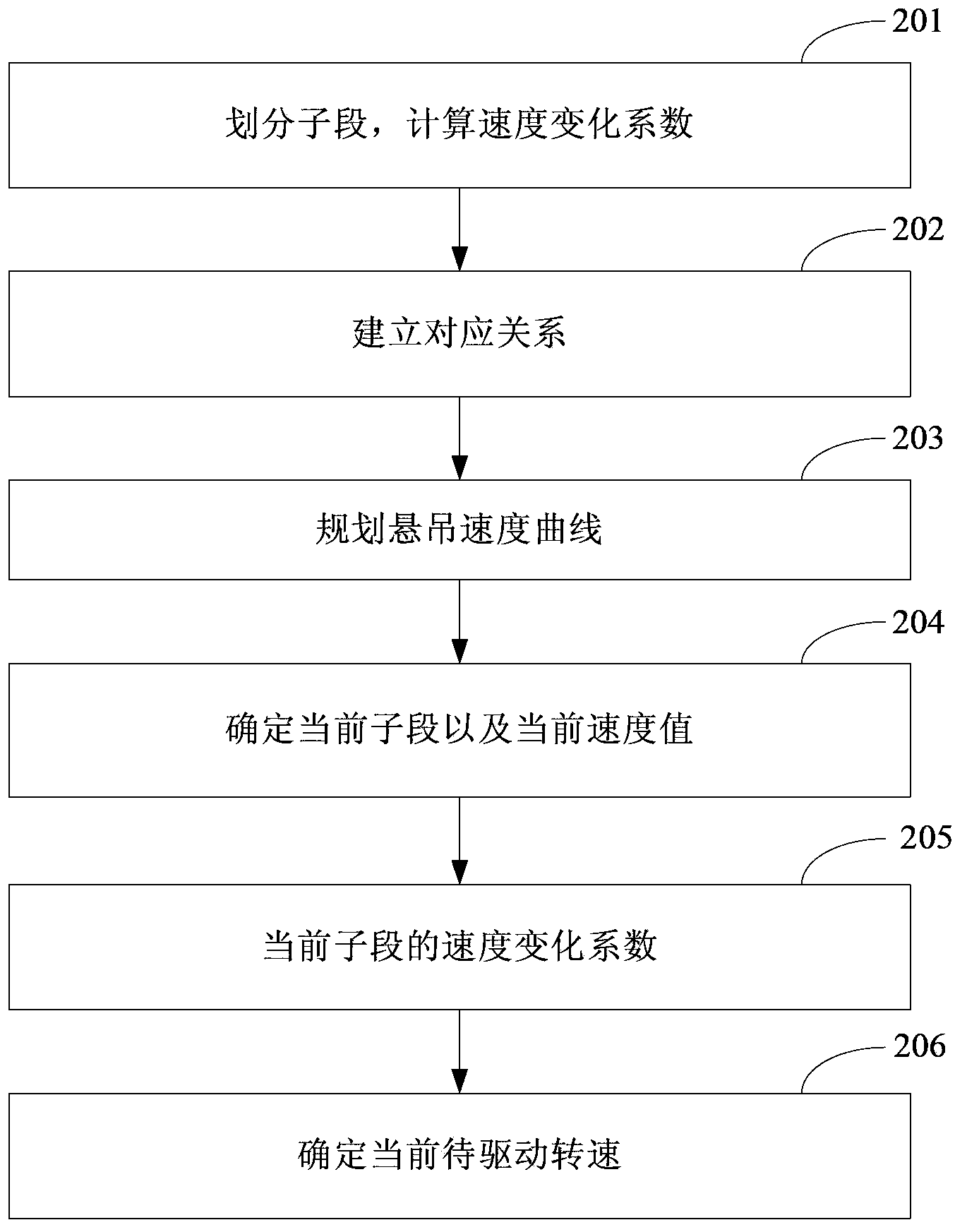
[0074] figure 2 It is an exemplary flow chart of the speed regulation control method of the conical runner in the embodiment of the present invention. Such as figure 2 As shown, the method includes the following steps:

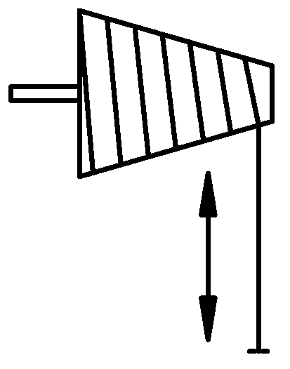
[0075] Step 201: Divide the conical runner into a plurality of sub-sections along the direction of the rotation axis, and calculate the speed variation coefficient of each sub-section relative to a selected reference sub-section.

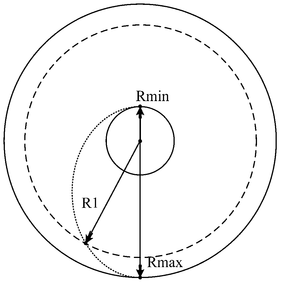
[0076] Figure 3a and Figure 3b A schematic diagram of the subsection division of the conical runner is shown. In the specific division, it can be divided according to the accuracy requirement. For example, according to the principle that each software scanning cycle corresponds to a sub-section, the conical runner can be evenly divid...


PUM


Abstract

The invention discloses a speed regulation method and device of a conical wheel. The method comprises dividing the conical wheel into a plurality of subsegments in the direction of a rotating shaft and calculating the speed change coefficient of every subsegment relative to a selected reference subsegment; establishing the corresponding relationship of every subsegment, the speed change coefficient of every subsegment and every pendant position value of a hanging rope wound on the conical wheel; scheduling a hanging speed curve which enables the hanging rope to meet the smooth operating requirements; during every control cycle of operation starting and the operation process, determining a current subsegment corresponding to the pendant position of the hanging rope to determine the current speed on the hanging speed curve; according to the corresponding relationship, determining the speed change coefficient of the current subsegment; according to the current speed and the speed change coefficient of the current subsegment, determining the current rotating speed to be driven of the conical wheel. The speed regulation method and device can achieve smooth and flat operation speed of an overhang end.

Description

technical field [0001] The invention relates to the technical field of equipment control, in particular to a speed regulation control method and device for a conical runner, and a medical equipment. Background technique [0002] Spring balancers are usually used in many applications that require suspended objects to move up and down, such as various assembly lines, and X-ray machines that need to suspend ball tubes and beamers for lifting movements. A suspension rope (such as a steel wire rope) is wound around the runner in the spring balancer, and the free end of the suspension rope, that is, the suspension end, is used to connect with the object to be suspended (referred to as the suspension object). The spring balancer mainly uses the energy stored in its internal coil spring to make the pulling force of the suspension rope and the gravity of the suspended object cancel each other, so that the object is in a weightless state. In this way, when the running wheel in the sp...

Claims


Application Information

Patent Timeline
Patent Type & Authority Applications(China)
IPC IPC(8): B66D1/46A61B6/00A61B6/03A61B5/055
Inventor 钱士坤王云平俞峰
Owner SIEMENS SHANGHAI MEDICAL EQUIP LTD
Why Eureka
Try Eureka