Control valve for coal gas

A technology for controlling valves and gas, which is applied in the control of combustion, valve configuration, gaseous fuel supply/distribution, etc., and can solve problems such as gas explosion noise

Inactive Publication Date: 2003-08-27
JAPAN CONTROL INDS
View PDF0 Cites 0 Cited by
  • Summary
  • Abstract
  • Description
  • Claims
  • Application Information

AI Technical Summary

Problems solved by technology

[0002] In prior art gas nozzles that act as switches in gas boilers or the like, the pressure may sometimes rise to 4 times the required pressure (for exa...

Method used


Image

  • Control valve for coal gas
  • Control valve for coal gas
  • Control valve for coal gas

Examples


Embodiment Construction

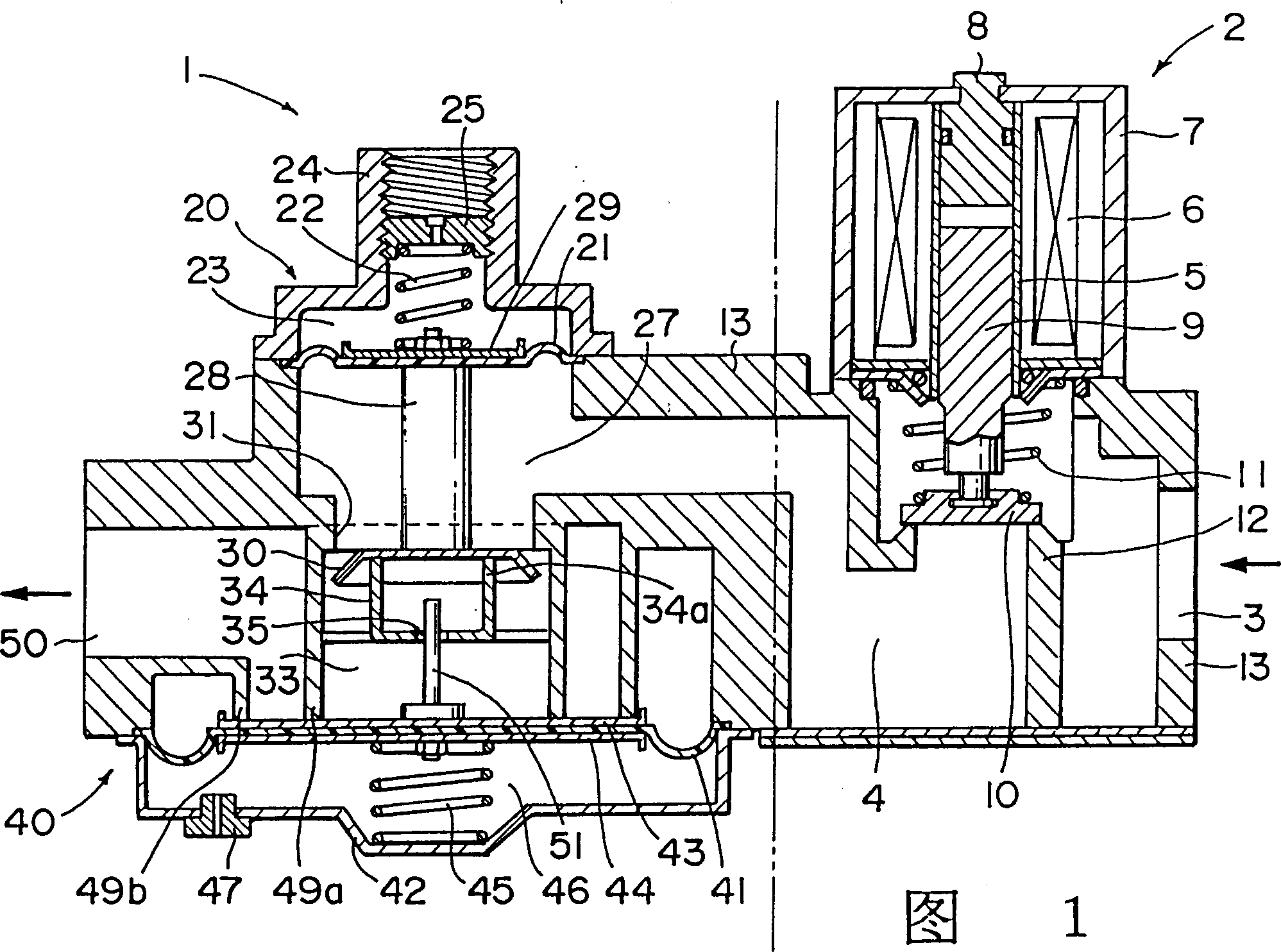
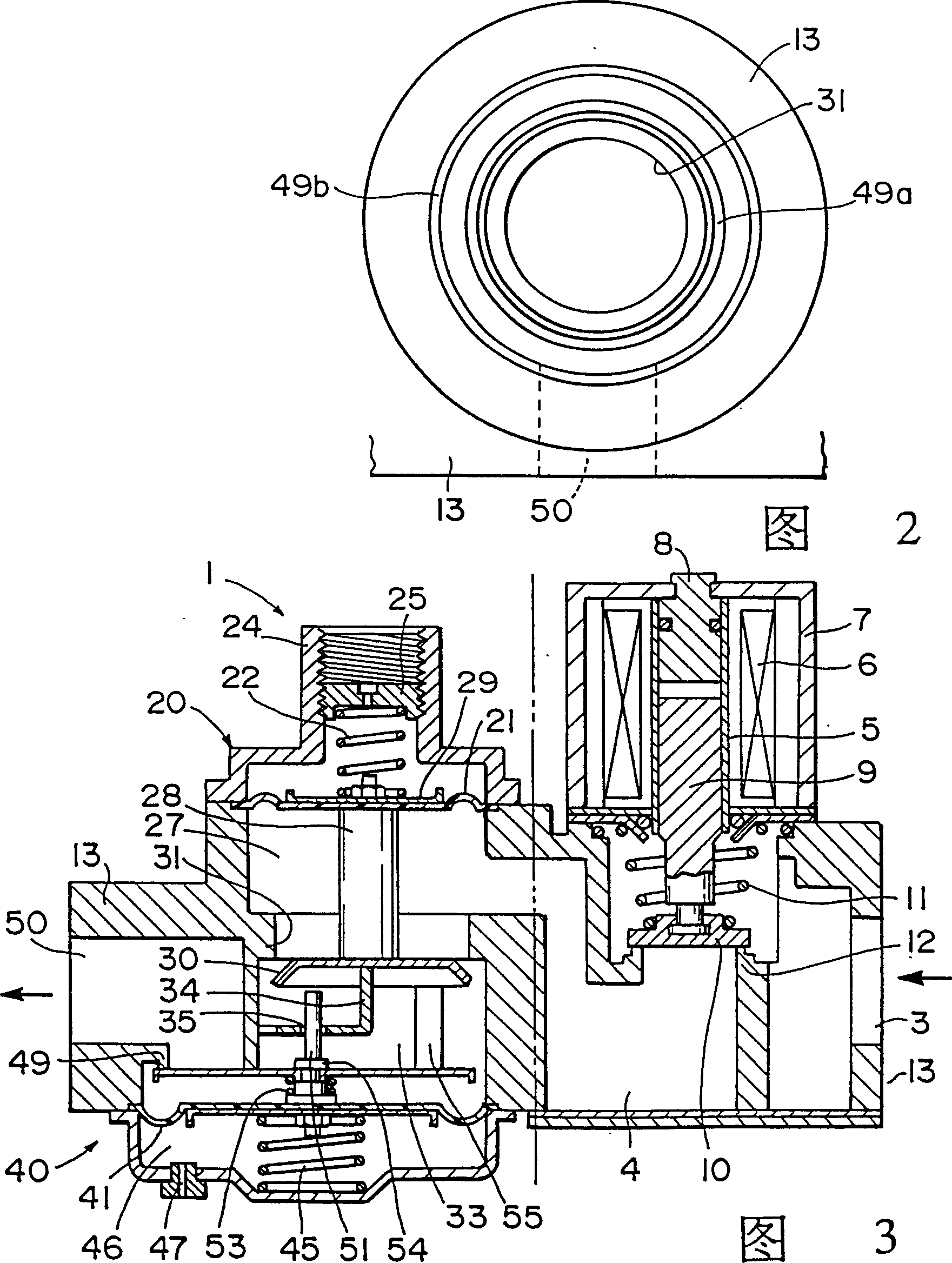
[0021] The following is an explanation of embodiments of the present invention with reference to the accompanying drawings. 1 and 2 show a first embodiment of the invention. The left area of ​​double-dot dash line is gas control valve 1, is also connected with gas control valve 1 and has an electric electromagnetic valve 2 (in the area on the right side) that controls gas supply (on / off). The solenoid valve 2 will be explained first and then the gas control valve 1 will be explained below.

[0022] The solenoid valve 2 is arranged on the gas pipeline 4 for opening and closing the pipeline, which extends from a gas inlet 3 to the main pressure chamber 27 of the governor 20 . Electromagnetic valve 2 comprises a guide sleeve 5, an electromagnetic coil 6 around guide sleeve 5, a cover 7 covering electromagnetic coil 6, a magnetic rod 8 fixed on guide sleeve 5 top made of magnetic material such as iron, a A plunger 9 made of magnetic material such as iron, which is set in the gui...


PUM


Abstract

With an aim to miniaturize a gas control valve which is provided with a speed governor and a soft igniter valve and to prevent that the diaphragm of the speed governor applies excessive stress to the speed governor when the controlling to the diaphragm is halted, the diaphragm of the speed governor, the diaphragm of the soft igniter valve and the stopper of the soft igniter valve are arranged face to face; one head face of a secondary depression box of the speed governor is blocked off by the diaphragm of the soft igniter valve; one head face of the secondary depression box of the speed governor is blocked off by the diaphragm of the soft igniter valve and a guide board is arranged inside the secondary depression box to limit the journey of the stopper of the valve of the speed governor.

Description

technical field [0001] The invention relates to a gas control valve, in particular to a gas control valve which acts as a switch when gas is supplied to a gas nozzle of a gas burning device. Background technique [0002] In prior art gas nozzles that act as switches in gas boilers or the like, the pressure may sometimes rise to 4 times the required pressure (for example, 70 mm of water column) within about 1 second after actuation, resulting in A large amount of gas flows through the nozzle and produces an explosion sound. To prevent this, soft ignition valves were developed. Next to one of these soft ignition valves, a so-called governor is placed which maintains the gas pressure at a specific level under constant operating conditions. [0003] As shown in Figure 5, the governor 100 is provided with a governor diaphragm 102, which receives the main pressure in the valve body 101, and a governor spring 103 is arranged on the non-main pressure side of the governor diaphragm...

Claims


Application Information

Patent Timeline
IPC IPC(8): F23L3/00F23K5/00F23N1/00
CPCF23K5/007F23K2900/05002
Inventor 佐佐木伸幸
Owner JAPAN CONTROL INDS
Why Eureka
Try Eureka