Clamp device

A technology of clamping device and clamping rod, applied in the direction of clamping device, positioning device, clamping, etc., can solve the problems of increasing and reducing the risk of productivity

Active Publication Date: 2011-05-18
CKD
View PDF0 Cites 0 Cited by
  • Summary
  • Abstract
  • Description
  • Claims
  • Application Information

AI Technical Summary

Problems solved by technology

When the waiting position of the unclamped fixture is too far from the workpiece, there is an increased risk of reduced productivity due to the time it takes to transition the fixture from the clamped to the unclamped state

Method used


Image

  • Clamp device
  • Clamp device
  • Clamp device

Examples


no. 1 example

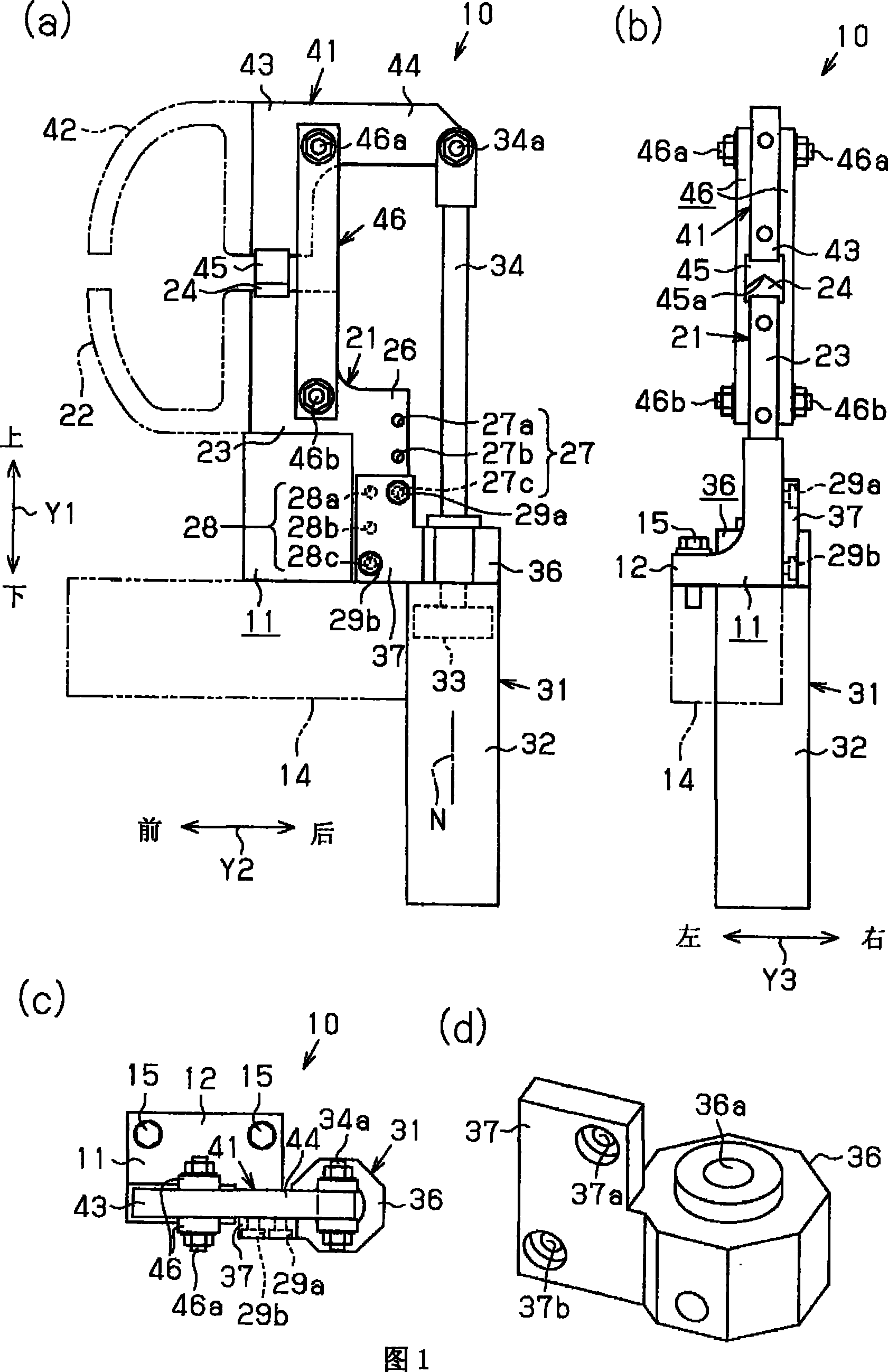
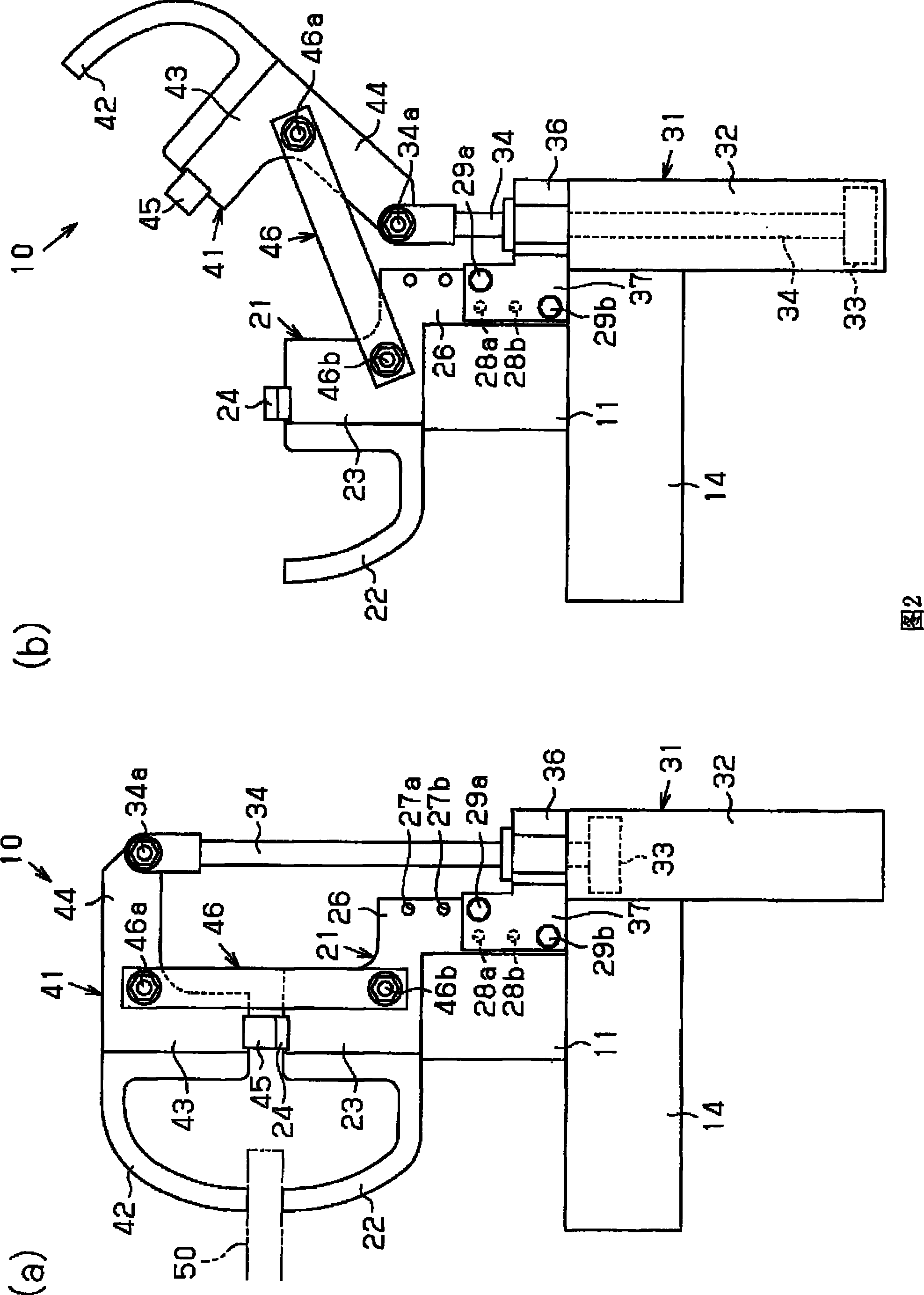
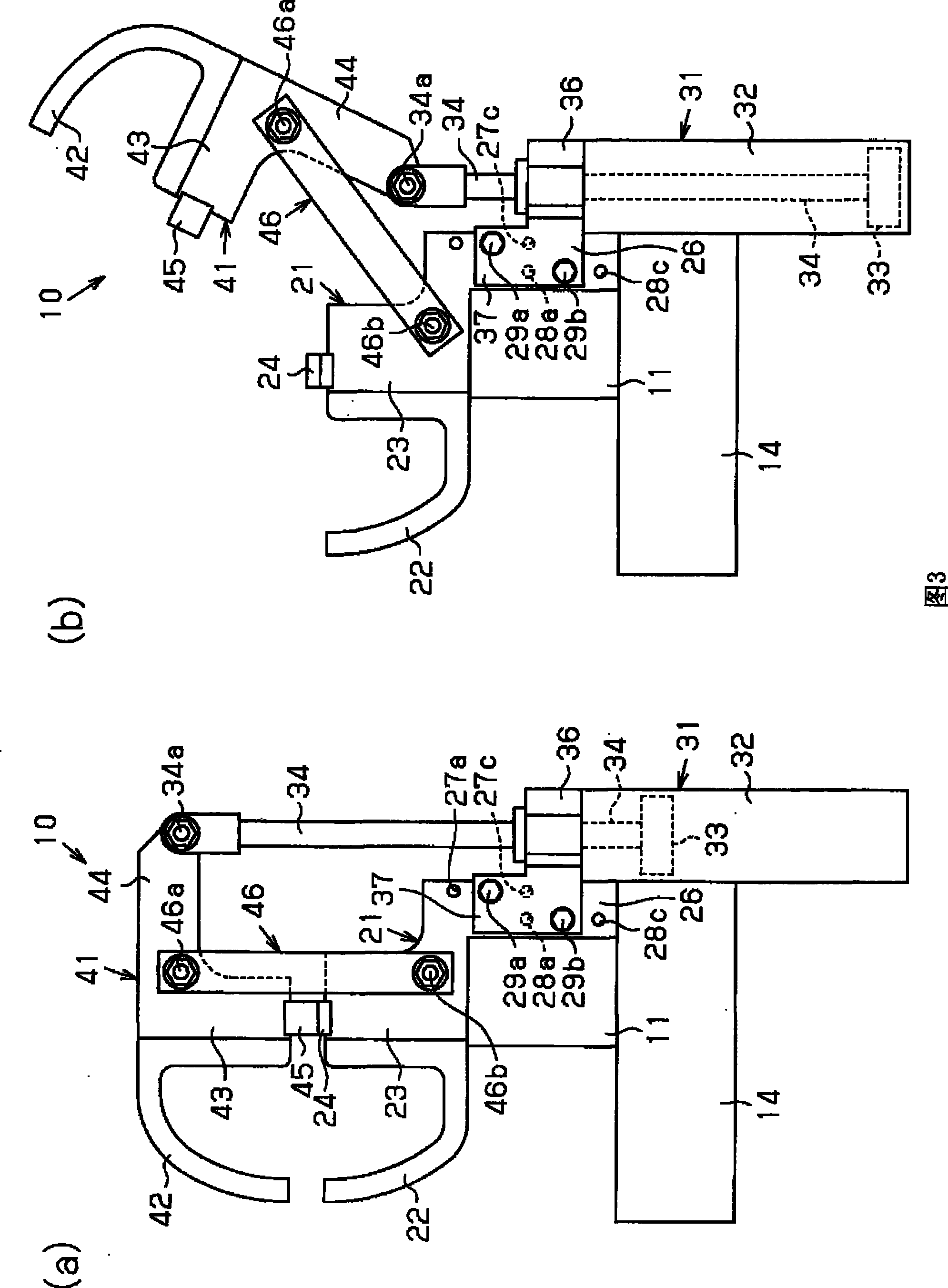
[0044] Hereinafter, a clamping device according to a first embodiment of the present invention will be described with reference to the drawings.

[0045] As shown in FIGS. 1( a ) to 1 ( c ), the clamping device 10 has a steel fixing portion 11 for fixing the clamping device 10 on a frame 14 . The fixing part 11 is L-shaped and has a base part 12 and a bottom 21 , the base part 12 extends laterally along a horizontal plane at the lower part of the fixing part 11 , and the bottom 21 is formed vertically upward from the base part 12 . The base plate portion 12 has a pair of front and rear holes (not shown) into which a pair of bolts 15 are inserted, and the base plate portion 12 is fixed to the frame 14 with the pair of bolts 15 passing through the holes.

[0046] The bottom 21 is formed in a flat plate shape so as to extend in the vertical and front-rear directions. The second rod attachment portion 23 corresponding to the front end of the bottom 21 is attached to the rear end ...

no. 2 example

[0077] Next, a second embodiment of the present invention will be described with reference to FIGS. 5( a ) to 8 . The same elements in the second embodiment as those in the first embodiment are given the same reference numerals, and descriptions thereof are omitted.

[0078] The clamping device 60 shown in Fig. 5 (a) and 5 (b) has the plate-like bottom 61 that extends along vertical direction and front-rear direction and has steel fixing part 62, and this steel fixing part 62 is screwed on by bolt 63a and A nut 63 b on the bolt 63 a is fixed to the right side surface of the bottom 61 . The clamp device 60 is fixed to the frame 14 indicated by the two-dot chain line in FIGS. 5( a ) and 5 ( b ) through a fixing portion 62 . Alternatively, the fixing portion 62 may be fixed on both the right side surface and the left side surface of the bottom 61 , and the clamping device 60 is fixed to the frame 14 through the two fixing portions 62 .

[0079] A second clamp lever 64 indicated...


PUM


Abstract

Provided is a lightweight and compact clamp device in which the waiting position of a first clamp lever at the time when the clamp device is unclamped can be easily adjusted by a simple structure. The clamp device (10) comprises a base (21), a cylinder actuator (31) mounted on the base (21) and capable of performing linear motion, and the first clamp lever (42). Based on the linear motion of the cylinder actuator (31), the arm (41) rotates the first clamp lever (42) in the direction to move near to and away from a second clamp lever (22). A mounting means for changing the mounting position ofthe cylinder actuator (31) on the base (21) along the direction of the linear motion of the cylinder actuator (31) is provided between the base (21) and the cylinder actuator (31).

Description

technical field [0001] The present invention relates to a clamping device for temporarily clamping workpieces, such as automobile parts to be processed at the production site, and in particular to a clamping device for workpieces between a first clamping rod and a second clamping rod Tightening or loosening clamps. Background technique [0002] Such a clamping device is disclosed in Patent Document 1, for example. In the clamping device, a clamping shaft perpendicular to the desktop on which the workpiece is installed is provided, and the workpiece is fixed on the table by a clamp arranged on the clamping shaft. The clamping device is provided with a horizontal position adjustment unit and a height adjustment unit, the horizontal position adjustment unit is used to move the clamping shaft on the table and fix the clamping shaft at a predetermined position, and the height adjustment unit is used to adjust the table top distance from the fixture. [0003] The height adjusti...

Claims


Application Information

Patent Timeline
Patent Type & Authority Patents(China)
IPC IPC(8): B23Q3/06
CPCB25B5/006B25B5/122B25B5/061B23Q3/082B23Q2703/04
Inventor 佐野博
Owner CKD
Why Eureka
Try Eureka