
buffer brake

A buffer braking, large-diameter technology, applied in shock absorbers, shock absorbers, steering control, etc., can solve problems such as wear and achieve the effect of suppressing sliding wear

Active Publication Date: 2021-06-01
NOK CORP
View PDF10 Cites 0 Cited by
  • Summary
  • Abstract
  • Description
  • Claims
  • Application Information

AI Technical Summary

Problems solved by technology

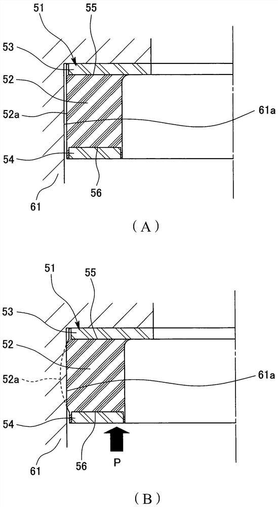
Also, as described above, even after the elastic body 52 comes into contact with the case 61, the movable-side end portion 56 continues to be displaced, so the elastic body 52 slides at the movable-side large-diameter portion 51C, and wear due to sliding occurs.

Method used


Image

  • buffer brake
  • buffer brake
  • buffer brake

Examples


no. 1 example

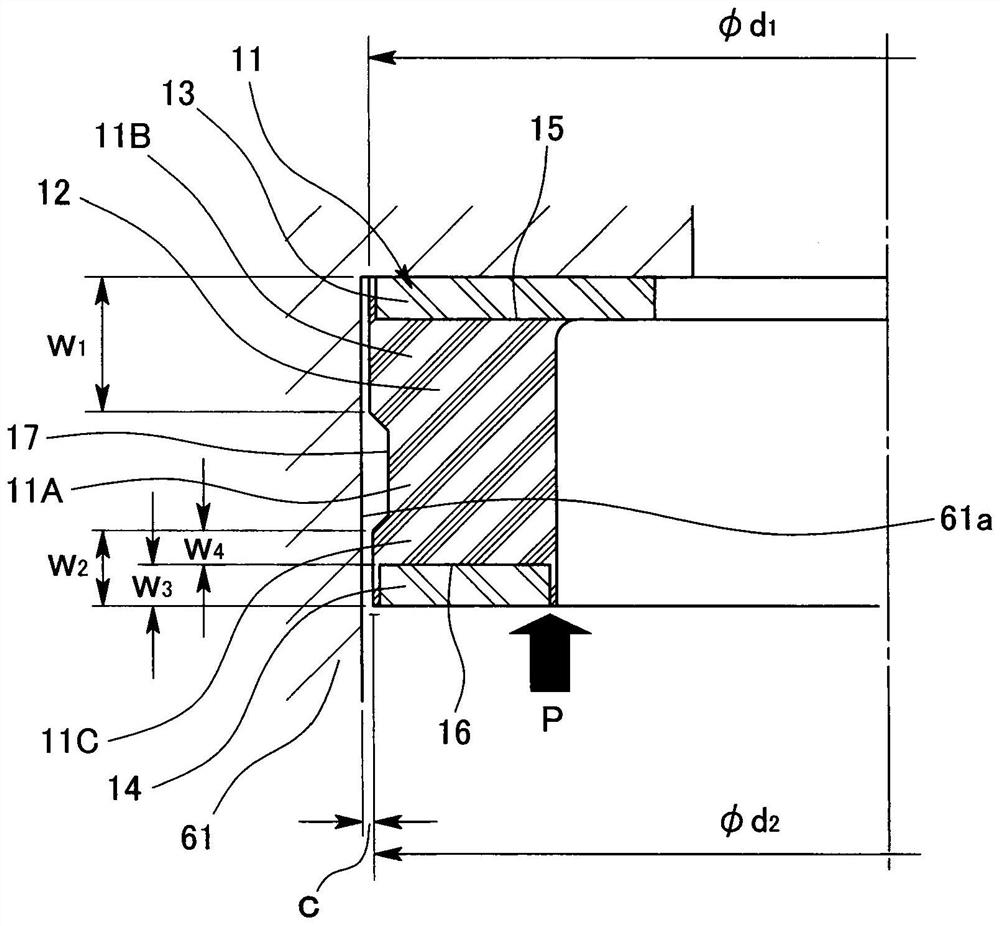
[0037] Such as figure 1 As shown, the buffer brake 11 according to this embodiment has a cylindrical elastic body 12 made of a predetermined rubber-like elastic body, and one axial end (the upper end in the figure) of the cylindrical elastic body 12 is connected to the annular The fixed side metal fitting 13 is connected to the fixed side metal fitting 13 and the other axial end portion (the lower end portion in the figure) is connected to the annular movable side metal fitting 14 . One end portion (hereinafter also referred to as the fixed side end portion 15 ) of the connection fixed side metal fitting 13 is fixed to the case 61 as a mating member. The other end portion (hereinafter also referred to as the movable side end portion 16 ) of the connecting movable side metal fitting 14 collides with a shaft (not shown) as an operation member and is displaced together with the shaft.

[0038] An annular recess 17 is provided on the outer peripheral surface of the elastic body ...

no. 2 example

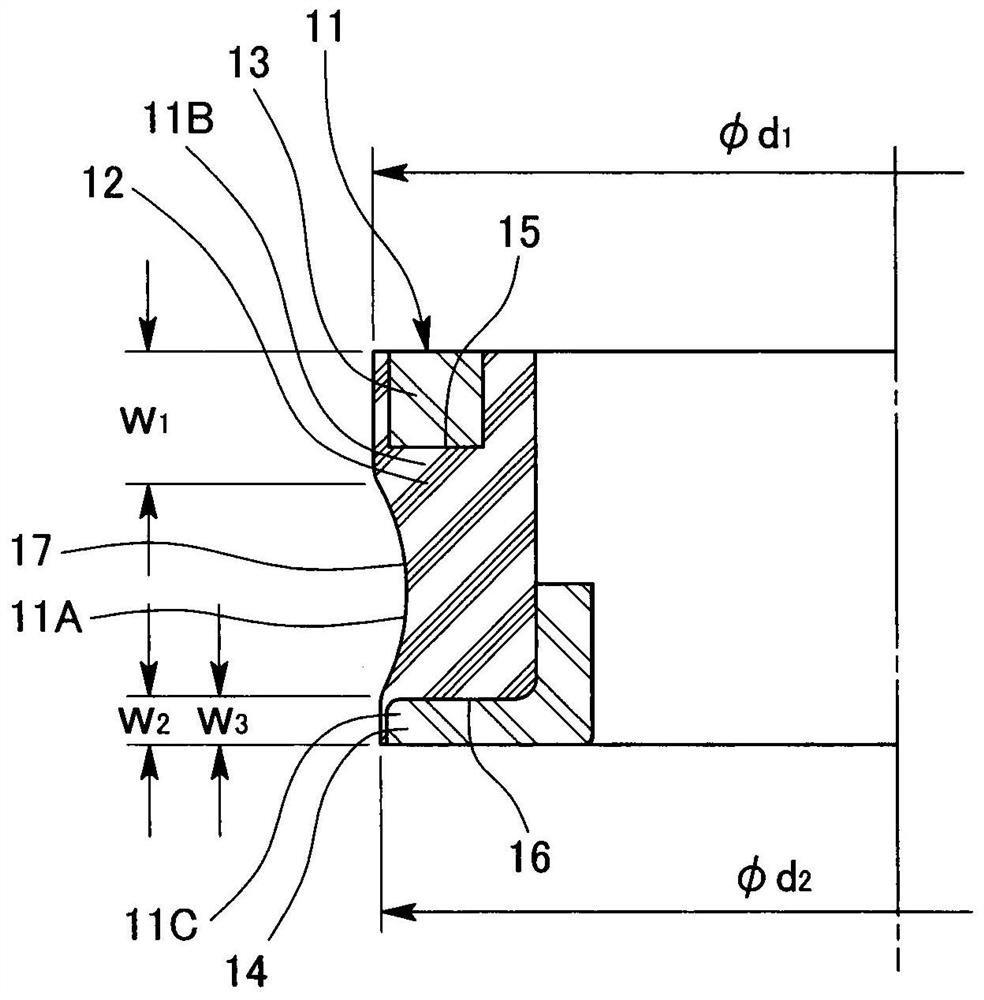
[0044] It should be noted that, in the first embodiment described above, the axial width w of the movable side large-diameter portion 11C 2 is the axial width (thickness) w of the movable side metal fitting 14 3 and the axial width w between the recess 17 in the elastic body 12 and the movable side metal fitting 14 4 The sum, due to the axial width w of the movable side large-diameter portion 11C 2 becomes smaller, so this makes the axial width w between the recess 17 in the elastic body 12 and the movable side metal fitting 14 4 It is also arranged to be small, but only the axial width (thickness) w of the movable side metal fitting 14 can 3 Set the axial width w of the movable side large-diameter portion 11C 2 , in this case, the axial width w between the recess 17 in the elastic body 12 and the movable side metal fitting 14 4 is set to zero.

[0045] As a second embodiment, in such as figure 2 In the buffer brake 11 shown, from this point of view, only the axial widt...


PUM


Abstract

The present invention provides a buffer brake which can suppress as much as possible sliding wear caused by contact between an elastic body and a mating member such as a case in a structure in which a concave portion is provided on the outer peripheral surface of the elastic body. In order to achieve this purpose, an annular recess is provided on the outer peripheral surface of a cylindrical elastic body that is connected to the fixed side metal fitting at one end and the movable side metal fitting at the other end, thereby dividing the buffer brake into small parts formed by the recesses. Three parts: a diameter portion, a fixed-side large-diameter portion positioned on a fixed side relative to the concave portion, and a movable-side large-diameter portion positioned on a movable side relative to the concave portion. Also, the outer diameter of the movable side large diameter portion is set to be smaller than the outer diameter of the fixed side large diameter portion, and the axial width of the movable side large diameter portion is set to be smaller than the axial width of the fixed side large diameter portion .

Description

technical field [0001] The invention relates to a buffer brake with buffer function and braking function. The cushion brake of the present invention is incorporated into, for example, a steering device in the field of automobile equipment, or used in the field of industrial equipment. Background technique [0002] So far, known as image 3 (A) The buffer brake 51 shown. This cushion stopper 51 has a cylindrical elastic body 52, one end (upper end in the figure) of the elastic body 52 is connected to the fixed side metal fitting 53, and the other end (lower end in the figure) is connected to the movable side metal fitting 54. connect. One end portion (hereinafter also referred to as the fixed side end portion 55 ) of the connection fixing side metal fitting 53 is fixed to the housing 61 as a fitting member. The other end portion (hereinafter also referred to as the movable side end portion 56 ) of the connecting movable side metal fitting 54 collides with a shaft (not show...

Claims


Application Information

Patent Timeline
Patent Type & Authority Patents(China)
IPC IPC(8): F16F7/00B62D3/12
CPCB62D3/12F16F7/00F16F1/3732B62D1/195F16F2234/02F16F2236/04
Inventor 花田祐树
Owner NOK CORP
Learn More