
Laser marking device with distance measurement function and laser marking method

A technology of laser marking and ranging device, applied in laser welding equipment, welding equipment, metal processing equipment and other directions, can solve the problems of uneven laser marking depth on product surface, inability to product uniformity, laser marking and other problems

Inactive Publication Date: 2016-08-17
SUZHOU ENOUXI INTELLIGENT TECH CO LTD
View PDF6 Cites 5 Cited by
  • Summary
  • Abstract
  • Description
  • Claims
  • Application Information

AI Technical Summary

Problems solved by technology

[0002] Existing laser marking devices usually can only perform uniform laser marking on the flat surface of the product, but cannot perform uniform laser marking on products with irregular shapes or uneven surfaces. If laser marking is forced, it will The depth of laser marking on the surface of the product is uneven and there are many defects

Method used


Image

  • Laser marking device with distance measurement function and laser marking method

Examples


Embodiment

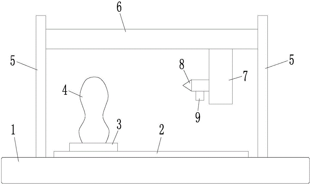
[0014] Embodiment: a distance-measuring laser marking device, comprising a frame 1, a workbench 2 fixedly connected to the frame 1, a fixture 3 arranged on the workbench 2 and used to clamp a product 4 to be marked, The laser marking head 8 that can be moved up and down, left and right, and forward and backward on the frame 1, the transmission mechanism that drives the laser marking head 8 to move, is fixedly connected with the laser marking head 8, and is used to detect the laser marking head 8 and the laser marking head 8. The distance measuring device 9 that marks the distance between the products 4, is connected with the signal of the distance measuring device 9 and controls the controller that the laser marking head 8 moves by the distance measured by the distance measuring device 9 (not shown in the accompanying drawings) ).

[0015] Specifically, the distance measuring device 9 is a distance sensor.

[0016] In a more preferred embodiment, the jig 3 is rotatably arrang...


PUM


Abstract

The invention discloses a laser marking device with a distance measurement function and a laser marking method. The laser marking device with the distance measurement function comprises a machine frame, a workbench, a clamp, a laser marking head, a transmission mechanism, a distance measurement device and a controller, wherein the workbench is fixedly connected with the machine frame; the clamp is arranged on the workbench and used for clamping a product to be marked; the laser marking head is arranged on the machine frame and can move up and down, left and right, and front and back; the transmission mechanism is used for driving the laser marking head to move; the distance measurement device is fixedly connected with the laser marking head and used for detecting the distance between the laser marking head and the product to be marked; and the controller is in signal connection with the distance measurement device and used for controlling the laser marking head to move according to the distance measured by the distance measurement device.

Description

technical field [0001] The invention relates to a distance-measuring laser marking device and a marking method. Background technique [0002] Existing laser marking devices usually can only perform uniform laser marking on the flat surface of the product, but cannot perform uniform laser marking on products with irregular shapes or uneven surfaces. If laser marking is forced, it will As a result, the depth of laser marking on the surface of the product is uneven, and there are many defects. Contents of the invention [0003] In order to solve the above technical problems, the purpose of the present invention is to provide a laser marking device and marking method that can adjust the distance between the laser marking head and the product to be marked in real time, thereby ensuring uniform marking depth. [0004] A distance-measuring laser marking device proposed by the present invention: includes a frame, a workbench fixedly connected to the frame, a fixture set on the wo...

Claims


Application Information

Patent Timeline
Patent Type & Authority Applications(China)
IPC IPC(8): B23K26/362B23K26/70
CPCB23K26/361B23K26/702
Inventor 高磊
Owner SUZHOU ENOUXI INTELLIGENT TECH CO LTD
Learn More