Eureka AIR delivers breakthrough ideas for toughest innovation challenges, trusted by R&D personnel around the world.
Electric control marking system for electrocorrosion marking production line
What is Al technical title?
Al technical title is built by PatSnap Al team. It summarizes the technical point description of the patent document.
A production line, electro-corrosion technology, used in typewriters, printing devices, printing, etc., can solve the problems of marking fluid flowing on the work surface and workpiece, poor consistency of marking marks, and burning of electrical equipment by users, so as to prevent marking. The effect of fluid flow, uniform marking and low labor intensity of workers
Active Publication Date: 2015-11-11
鞍山市庆龙机电有限公司
View PDF5 Cites 0 Cited by
Summary
Abstract
Description
Claims
Application Information
AI Technical Summary
This helps you quickly interpret patents by identifying the three key elements:
Problems solved by technology
Method used
Benefits of technology
Problems solved by technology
[0007] Although the above two kinds of marking heads can realize automatic delivery of marking liquid, there are still some shortcomings in the actual use process. Since the marking head only has a marking liquid injection line, the marking liquid injection line and The marking head has only one interface, so the marking liquid input into the marking head is uneven, resulting in poor marking consistency and low yield during work. If too much marking liquid is input into the marking liquid injection line, it will cause The marking fluid flows on the work surface and the workpiece, and the workpiece and the work surface need to be cleaned frequently, which not only affects the work efficiency, but also increases the labor intensity of the workers. If the cleaning is not timely, the user often burns the electrical equipment under the table, such as PLC, etc. users cause great loss
Method used
Image
Click on the blue label to locate the original text in one second.
Reading with bidirectional positioning of images and text.
Examples
Embodiment Construction
[0028] The specific implementation manner of the present invention will be described below in conjunction with the accompanying drawings.
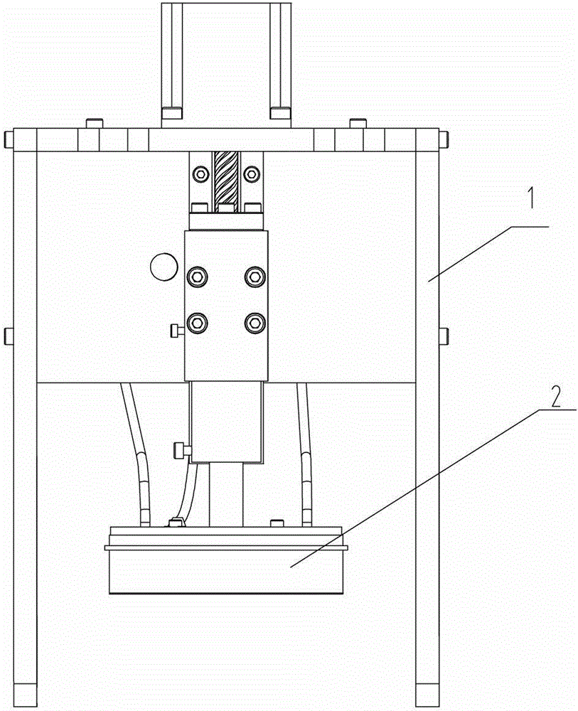
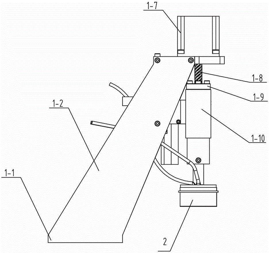
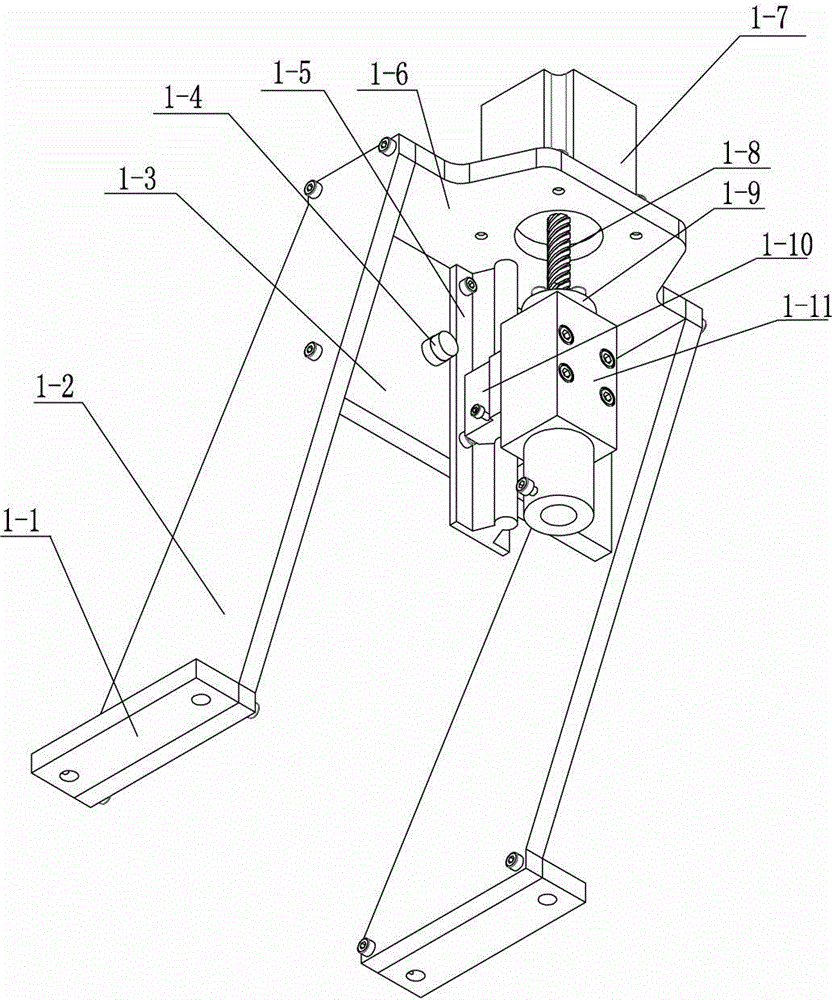
[0029] Such as figure 1 , figure 2 , image 3 , Figure 4 and Figure 5 As shown, the electrical control marking system for the electro-corrosion marking production line of the present invention includes a marking actuator 1 and a marking head 2 connected to the marking actuator 1, and the marking actuator 1 includes a fixed frame and The marking drive device installed on the fixed frame, the described marking head includes plexiglass liner 2-4, fixed frame 2-8, graphite block 2-5, carbon felt 2-7, conductive mesh 2-6, The electrode sheet 2-3, the marking head positioning sleeve 2-10 and the wire 2-1 connected with the electrode sheet 2-3 have internal threaded holes at both ends of the plexiglass lining plate 2-4. Block 2-5 is also provided with a threaded hole at the position corresponding to the plexiglass liner 2-4, and the elect...
PUM
Abstract
The invention relates to an electric control marking system for an electrocorrosion marking production line. The electric control marking system comprises a marking executing mechanism and a marking head connected with the marking executing mechanism. The marking executing mechanism comprises a fixing frame and a marking driving device arranged on the fixing frame. The electric control marking system is characterized in that the fixing frame is an oblique-pulling type fixing frame, the marking driving device comprises a stepping motor, a lead screw, a sliding sleeve, a straight line bearing and a sliding track, and the marking head comprises an organic glass lining plate, a fixing frame, a graphite block, carbon felt, a conducting net, an electrode piece, a marking head locating sleeve, a lead wire connected with a pole piece with electricity, a marking liquid injection pipe, a marking liquid sucking pipe, a filter and a marking liquid storage and peristaltic pump. The electric control marking system has the advantages that stroke is accurate, pressure is constant, the structure is stable, locating is accurate, operation is convenient, model changing is convenient, speed is high, production efficiency is high, worker operation labor intensity is low, liquid providing is even, circulating using is achieved, liquid sucking force is strong, liquid flowing is avoided, energy is saved, and environment is protected.
Description
technical field [0001] This patent belongs to the technical field of metal marking, and in particular relates to an electric control marking system for an electric corrosion marking production line. Background technique [0002] With the development of modern technology, electrocorrosion products have been applied in more and more industries. Electrocorrosion marking has been widely promoted and applied due to its advantages of fast marking speed, less consumption and environmental protection. The marking system for electro-corrosion is mainly composed of a marking actuator and a header connected to the marking actuator. [0003] The traditional marking actuator mainly includes a fixed frame and a marking head drive device connected to the fixed frame. Beam-type fixed frame, the base is connected to the vertical rod and fixed on the worktable, the connecting block connects the vertical rod and the horizontal rod through locking screws, the driving device is usually driven ...
Claims
Application Information
Patent Timeline
Application Date:The date an application was filed.
Publication Date:The date a patent or application was officially published.
First Publication Date:The earliest publication date of a patent with the same application number.
Issue Date:Publication date of the patent grant document.
PCT Entry Date:The Entry date of PCT National Phase.
Estimated Expiry Date:The statutory expiry date of a patent right according to the Patent Law, and it is the longest term of protection that the patent right can achieve without the termination of the patent right due to other reasons(Term extension factor has been taken into account ).
Invalid Date:Actual expiry date is based on effective date or publication date of legal transaction data of invalid patent.