
Mold locking mechanism

A mold clamping and mold technology, applied in the field of mold clamping mechanism, can solve the problems of volume expansion, large axial force of locking teeth, bending, etc., and achieve the effect of reducing instantaneous impulse

Inactive Publication Date: 2016-09-07
CIXI SHENGYI MOLD
View PDF5 Cites 1 Cited by
  • Summary
  • Abstract
  • Description
  • Claims
  • Application Information

AI Technical Summary

Problems solved by technology

[0003] However, due to the large amount of heat generated during the molding process of the injection mold, the mold and related parts have a certain degree of volume expansion.
Therefore, when the mold is opened, when the clamping cylinder reversely pushes the clamping sleeve, the lock tooth and the lock hole will receive a large impulse when the lock tooth is in contact with the lock hole, so the axial force of the lock tooth is extremely large, and in the process of repeated mold opening and closing It is easy to wear and tear, which will affect the clamping accuracy, and even bend and break if it is serious.

Method used


Image

  • Mold locking mechanism
  • Mold locking mechanism
  • Mold locking mechanism

Examples


Embodiment Construction

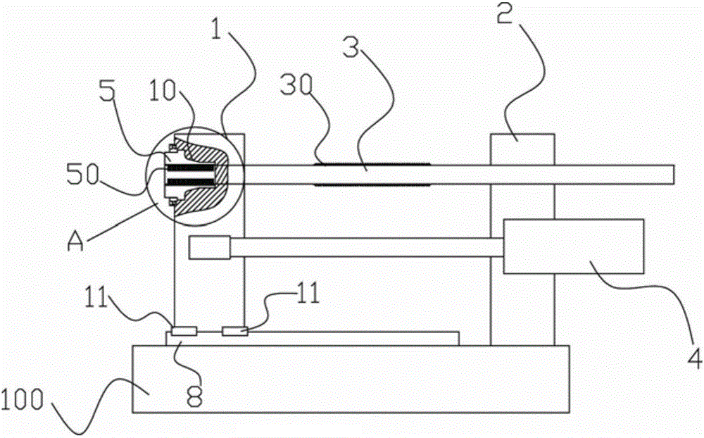
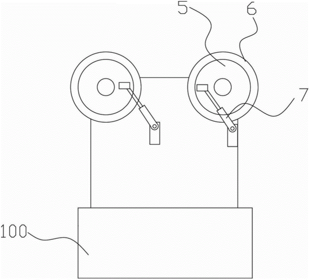
[0014] Below in conjunction with accompanying drawing and specific embodiment the present invention will be described in further detail: Figure 1-5 As shown, the two-plate clamping mechanism includes a base 100, a movable template 1 and a fixed template 2, and the left side of the base 100 (with attached figure 1 The left side in is defined as the left direction here) with a fixed template 2 erected, and on the base 100 toward the mold opening and closing direction (that is, the horizontal direction) is fixed with a tie rod part 3 for linear guidance, and the tie rod part 3 There are two tie rod parts 3 arranged at intervals, the movable template 1 is arranged on the tie rod parts in a manner that can move along the mold opening and closing direction, and sliding plates are fixedly arranged on both sides of the lower end of the moving film plate 1 . The block 11 is provided with a linear guide rail 8 matching the slider 11 on the base 100 .

[0015] It also includes a mold t...


PUM


Abstract

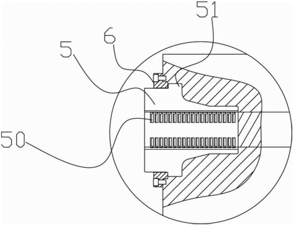
The invention discloses a mold locking mechanism. The mold locking mechanism comprises a base, a movable template, a fixed template, a pull rod part, a mold shifting oil cylinder, a mold locking sleeve arranged on the movable template, a locking hole on the mold locking sleeve, and a locking tooth matched with the locking hole on the pull rod part; and a lap of flange is arranged at the outer periphery of the mold locking sleeve. The mold locking mechanism further comprises a gland fixedly arranged on the mold locking sleeve; the gland has an end surface part leant against the flange; the end surface part includes inclined block parts uniformly arranged in the peripheral direction at intervals, and plane parts connected among all the inclined block parts; and inclined top parts matched with the inclined block parts are arranged on the flange. When a mold is opened, that is, when the locking tooth is deviated from the locking hole due to rotation of the mold locking sleeve, the inclined top parts arranged on the mold locking sleeve slide into the plane parts along the inclined block parts of the gland, so that the mold locking sleeve is backwards displaced by a distance to reduce the instant impulse of inserting the locking tooth in the locking hole in mold opening.

Description

technical field [0001] The invention relates to the technical field of molds, and more specifically, relates to a clamping mechanism for injection molds. Background technique [0002] The existing common clamping mechanism for injection molds includes a base, a movable platen and a fixed platen. On the fixed platen, a tie rod part for linear guidance is fixed toward the direction of mold opening and closing, and the movable platen is set in such a way that it can move along the direction of mold opening and closing. On the pull rod part, it also includes a mold-moving oil cylinder for pushing the movable template, a through hole is arranged on the movable template, and a mold locking sleeve is arranged in the through hole, and a mold locking sleeve is arranged in the mold locking The sleeve is provided with a lock hole, the tie rod part passes through the clamping sleeve, the lock tooth matching the lock hole is arranged on the tie rod part, and the push rod is arranged behi...

Claims


Application Information

Patent Timeline
Patent Type & Authority Applications(China)
IPC IPC(8): B29C45/68
CPCB29C45/68
Inventor 景伟德
Owner CIXI SHENGYI MOLD
Learn More